


Page 52
Epson Research and Development
Vancouver Design Center
SED1352
Hardware Functional Specification
X16-SP-001-16
Issue Date: 99/07/28
AUX[0Ah] bits 7-0 Screen 1 Display Line Count Bits [9:0]
AUX[0Bh] bits 1-0 These bits are the eight LSB of a 10-bit value used to determine the number of lines displayed for screen 1.
The remaining lines will automatically display from the Screen 2 Display Start Address. The 10-bit value
programmed is the number of display lines -1.
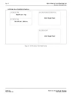
This register is used to enable the split screen display feature (single panel only) where two different
images can be displayed at the same time on one display.
For example; AUX[0Ah] = 20h for a 320x240 display system. The display will display 20h+1 = 33 lines
on the upper part of the screen as dictated by the Screen 1 Display Start Address Registers (AUX[06h] and
AUX[07h]), and 240 - 33 = 207 lines will be displayed on the lower part of the screen as dictated by the
Screen 2 Display Start Address Registers (AUX[08h] and AUX[09h]).
Two different images can be displayed when using a dual panel configuration by changing the Screen 2
Display Start Address. However, by using this method screen 2 is limited to the lower half of the display.
This register is ignored in dual panel mode.
bits 7-0
Addr Pitch Adjustment Bits [7:0]
These bits set the numerical difference between the last address of a display line, and the first address in
the following line.
If the Address Pitch Adjustment is not equal to zero, then a virtual screen is formed. The size of the virtual
screen is only limited by the available display memory. The actual display output is a window that is part
of the whole image stored in the display memory. For example, with 128K of display memory, a 640x400
16-gray image can be stored. If the output display size is 320x240, then the whole image can be seen by
changing display starting addresses through AUX[06h] and [07h], and AUX[08h] and [09h]. Note that a
virtual screen can be produced on either a single or dual panel.
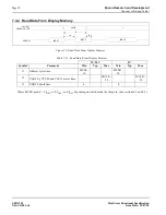
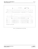
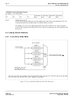
AUX[0Ah] Screen 1 Display Line Count Register (LSB)
I/O address = 1010b, Read/Write.
Screen 1
Display
Line Count
Bit 7
Screen 1
Display
Line Count
Bit 6
Screen 1
Display
Line Count
Bit 5
Screen 1
Display
Line Count
Bit 4
Screen 1
Display
Line Count
Bit 3
Screen 1
Display
Line Count
Bit 2
Screen 1
Display
Line Count
Bit 1
Screen 1
Display
Line Count
Bit 0
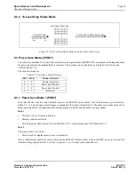
AUX[0Bh] Screen 1 Display Line Count Register (MSB)
I/O address = 1011b, Read/Write.
n/a
n/a
n/a
n/a
n/a
n/a
Screen 1
Display
Line Count
Bit 9
Screen 1
Display
Line Count
Bit 8
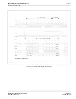
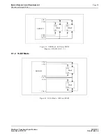
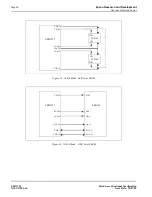
AUX[0Dh] Address Pitch Adjustment Register
I/O address = 1101b, Read/Write.
Addr Pitch
Adjustment
Bit 7
Addr Pitch
Adjustment
Bit 6
Addr Pitch
Adjustment
Bit 5
Addr Pitch
Adjustment
Bit 4
Addr Pitch
Adjustment
Bit 3
Addr Pitch
Adjustment
Bit 2
Addr Pitch
Adjustment
Bit 1
Addr Pitch
Adjustment
Bit 0