Epson Stylus Photo R280/R285/R290/Epson Artisan 50/Epson Stylus Photo T50/T59/T60/P50
Revision C
Chapter 4 Disassembly/Assembly
4.4.17 Front Paper Guide Assy (Disassembling the Printer Mechanism)
97
Confidential
5.
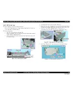
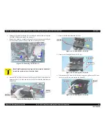
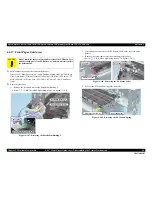
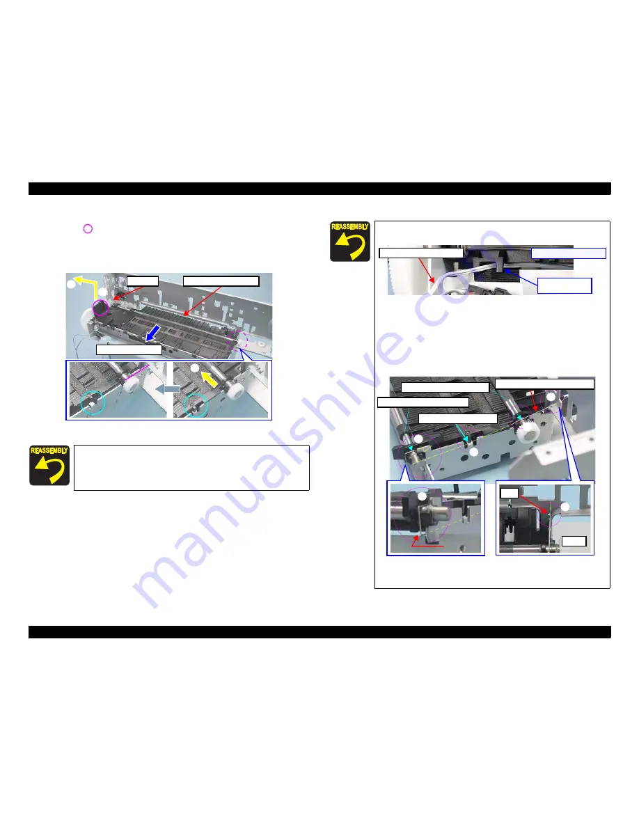
Remove the Front Paper Guide Assy, following the steps below.
(1) Lift
part to disengage the left side of the Front Paper Guide Assy.
(2) Slide the assy leftward little by little to disengage the right side of the assy.
(3) Remove the Front Paper Guide Assy while releasing its shaft from the cutout
of the rib on the left side of the Main Frame.
Figure 4-110. Removing the Front Paper Guide Assy
Lubrication is required. See the page given below for the
lubrication information.
Lubrication of Front Paper Guide Assy (p.123)
1
2
Removal Direction
Front Paper Guide Assy
Cutout
2
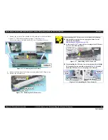
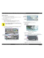
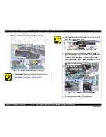
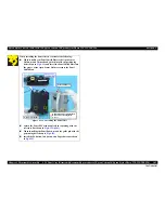
When installing the Front Paper Guide Assy, pull out the CDR
Tray Sensor cable as shown below.
Figure 4-111. Routing the CDR Tray Sensor Cable
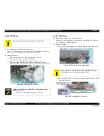
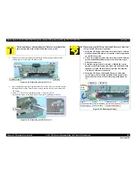
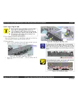
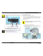
Attach the long foot of the EJ Ground Spring as follows; (1)
put it through the gap under the portion contacts with the EJ
Roller, (2) let it contact with the Main Frame, (3) let it contact
with the PF Roller shaft, (4) put it through the hole on the
frame. When finished, make sure the spring properly contacts
with (1), (2), (3), and (4) points.
Figure 4-112. Attaching the EJ Ground Spring
Be careful not to deform the EJ Ground Spring.
[Left Front Bottom Side]
Pull out the cable
from here
CDR Tray Sensor Cable
1
2
Contacts with PF Roller Shaft
Long foot of EJ Ground Spring
Contacts with Main Frame
4
3
Contacts with EJ Roller shaft
4
Hole
Gap
1
Summary of Contents for 50 - Artisan 50 - Printer
Page 8: ...Confidential C H A P T E R 1 PRODUCTDESCRIPTION ...
Page 22: ...Confidential C H A P T E R 2 OPERATINGPRINCIPLES ...
Page 29: ...Confidential C H A P T E R 3 TROUBLESHOOTING ...
Page 52: ...Confidential C H A P T E R 4 DISASSEMBLY ASSEMBLY ...
Page 103: ...Confidential C H A P T E R 5 ADJUSTMENT ...
Page 120: ...Confidential C H A P T E R 6 MAINTENANCE ...


