Epson Stylus Photo R280/R285/R290/Epson Artisan 50/Epson Stylus Photo T50/T59/T60/P50
Revision C
Chapter 4 Disassembly/Assembly
4.4.9 EJ Frame Assy (Disassembling the Printer Mechanism)
85
Confidential
8.
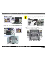
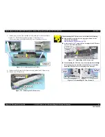
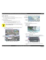
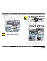
Remove the screws on the right and left sides, and remove the Front Frame.
•
Screw
: C.B.S. M3x6 (tightening torque: 7-9 kgf.cm)
(No.1)
(The numbers shown in the figure indicate the order of tightening the screws.)
Figure 4-75. Removing the Front Frame
9.
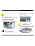
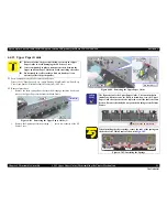
Release the CDR Sensor Cable from the cable guide of the EJ Frame Assy.
10.
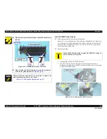
Remove the EJ Frame Assy.
Figure 4-76. Removing the EJ Frame Assy
Front Frame
1
Positioning hole
and Guide Pin
2
EJ Frame Assy
Removal Direction
Cable Guide
CDR Sensor Cable
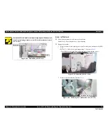
When installing the EJ Frame Assy, be careful of the following:
Lubrication is required. See the page given below for the
lubrication information.
Lubrication of EJ Frame Assy (p.123)
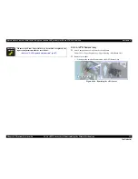
As shown in
Fig.4-77
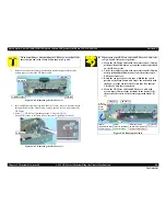
, insert the two bearings of the EJ Frame
Assy over the EJ Roller Shaft.
Figure 4-77. Reinstalling the EJ Frame Assy
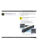
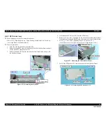
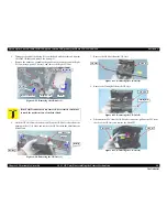
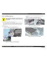
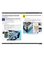
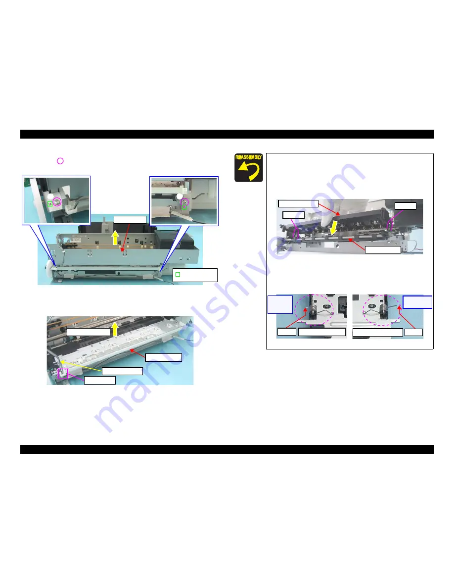
When installing the EJ Frame Assy, make sure that the Left/Right
EJ Frame Springs are attached as shown in
Fig.4-78
. Carefully
handle the EJ Frame Assy as the springs come off easily.
Figure 4-78. Reinstalling the Front Frame (1)
Bearing
Bearing
EJ Roller Shaft
EJ Frame Assy
Shorter
Left EJ Frame Spring
Right EJ Frame Spring
Longer
[Left Side]
Opposite
to HP
[Right Side]
HP Side
Summary of Contents for 50 - Artisan 50 - Printer
Page 8: ...Confidential C H A P T E R 1 PRODUCTDESCRIPTION ...
Page 22: ...Confidential C H A P T E R 2 OPERATINGPRINCIPLES ...
Page 29: ...Confidential C H A P T E R 3 TROUBLESHOOTING ...
Page 52: ...Confidential C H A P T E R 4 DISASSEMBLY ASSEMBLY ...
Page 103: ...Confidential C H A P T E R 5 ADJUSTMENT ...
Page 120: ...Confidential C H A P T E R 6 MAINTENANCE ...

