Epson Stylus Photo R280/R285/R290/Epson Artisan 50/Epson Stylus Photo T50/T59/T60/P50
Revision C
Chapter 4 Disassembly/Assembly
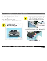
4.4.8 Ink System (Disassembling the Printer Mechanism)
82
Confidential
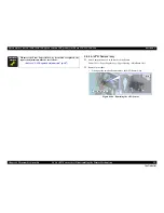
CDR Guide Sensor Removal
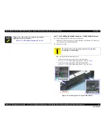
1.
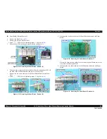
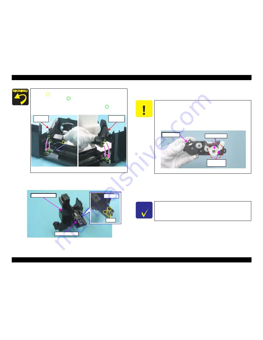
Disengage the two hooks on the back of the CDR Guide Sensor and remove
the CDR Guide Sensor.
Figure 4-66. Removing the CDR Guide Sensor
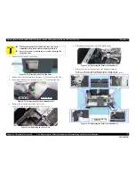
4.4.8 Ink System
Parts/Components need to be removed in advance
Printer Cover / Paper Support Assy / Upper Housing / Main Board Unit / Panel Assy /
Cover Open Sensor / Printer Mechanism
Removal procedure
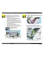
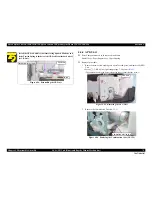
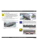
When installing the Left Guide Stacker, insert the rib indicated
with in
Fig.4-65
and match the positioning holes and guide
pins indicated with
(two pairs).
When installing the Right Guide Stacker, match the
positioning holes and guide pins indicated with
(two
pairs) in
Fig.4-65
.
Figure 4-65. Installing the Left / Right Guide Stacker
Right Guide
Stacker
Left Guide
Stacker
[Back Side]
Hooks
Right Guide Stacker
CDR Guide Sensor
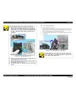
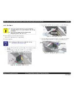
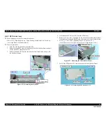
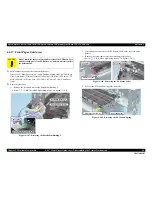
C A U T I O N
Take extra care not to spill ink and contaminate the
surroundings. Also, when removing the Waste Ink Tube, be
careful not to spill the ink.
Extra care must be taken to avoid injury from sharp edges of
the rib of the Main Frame.
Be careful not to drop and damage the shaft of the Carriage
Lock and the Torsion Spring, as they easily come off.
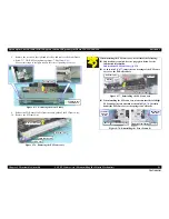
Figure 4-67. Ink System
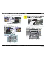
C H E C K
P O I N T
See the section given below on how to unlock the carriage.
•
“4.1.8 How to Unlock the Carriage”
Shaft of the
Carriage Lock
Torsion Spring
Pump Section
Pump Section
Summary of Contents for 50 - Artisan 50 - Printer
Page 8: ...Confidential C H A P T E R 1 PRODUCTDESCRIPTION ...
Page 22: ...Confidential C H A P T E R 2 OPERATINGPRINCIPLES ...
Page 29: ...Confidential C H A P T E R 3 TROUBLESHOOTING ...
Page 52: ...Confidential C H A P T E R 4 DISASSEMBLY ASSEMBLY ...
Page 103: ...Confidential C H A P T E R 5 ADJUSTMENT ...
Page 120: ...Confidential C H A P T E R 6 MAINTENANCE ...

