Epson Stylus Photo R280/R285/R290/Epson Artisan 50/Epson Stylus Photo T50/T59/T60/P50
Revision C
Chapter 4 Disassembly/Assembly
4.3.2 Panel Assy/ Cover Open Sensor (Removing Control Boards)
70
Confidential
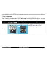
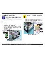
Cover Open Sensor Removal
1.
Remove the Panel Assy. (
p.67
)
2.
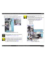
From the back of the Open Sensor Holder, disengage the hook of the Cover
Open Sensor, and remove the Cover Open Sensor pulling its rib out of the
hole by rotating the sensor in the direction of the arrow.
3.
Disconnect the connector from the Cover Open Sensor to remove the Cover
Open Sensor.
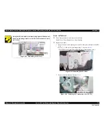
Figure 4-33. Removing the Cover Open Sensor
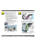
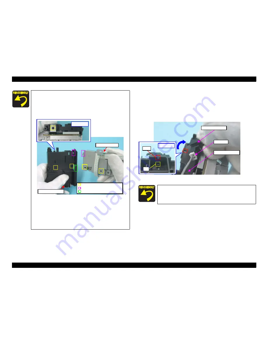
When installing the Panel Unit, be careful of the following:
When installing the Panel Shield Plate to the Open Sensor
Holder, match the hook and guide pins with the positioning
holes shown in
Fig.4-32
and insert the Panel Shield Plate into
the groove of the Open Sensor Holder to secure the Panel
Shield Plate.
Figure 4-32. Installing the Panel Unit
Attach the Panel FFC with double-sided tape along with the
reference line shown in
Fig.4-29 (p.69)
.
When installing the Panel Board, match the guide pin with the
positioning hole shown in
Fig.4-30
.
Install the PS button, Ink button and Paper button as shown in
Fig.4-31
.
[Upper Side]
Guide Pin and Positioning Hole
Hook and Positioning Hole
Groove
Open Sensor Holder
Panel Shield Plate
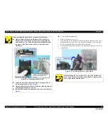
When installing the Cover Open Sensor, insert the rib shown in
Fig.4-33
into the hole of the Open Sensor Holder, and secure the
Cover Open Sensor with the hook.
Hook
Rib
[Back Side]
Open Sensor Holder
Connector
Cover Open Sensor
Summary of Contents for 50 - Artisan 50 - Printer
Page 8: ...Confidential C H A P T E R 1 PRODUCTDESCRIPTION ...
Page 22: ...Confidential C H A P T E R 2 OPERATINGPRINCIPLES ...
Page 29: ...Confidential C H A P T E R 3 TROUBLESHOOTING ...
Page 52: ...Confidential C H A P T E R 4 DISASSEMBLY ASSEMBLY ...
Page 103: ...Confidential C H A P T E R 5 ADJUSTMENT ...
Page 120: ...Confidential C H A P T E R 6 MAINTENANCE ...

