Epson Stylus Photo R280/R285/R290/Epson Artisan 50/Epson Stylus Photo T50/T59/T60/P50
Revision C
Chapter 4 Disassembly/Assembly
4.5.1 Panel Assy (Disassembly/reassembly procedures of Epson Artisan 50/Epson Stylus Photo T50/T59/T60/P50)
100
Confidential
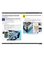
When Installing the Panel Assy, be careful of the following:
Tighten the screws in the order given in
Fig.4-116
.
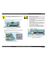
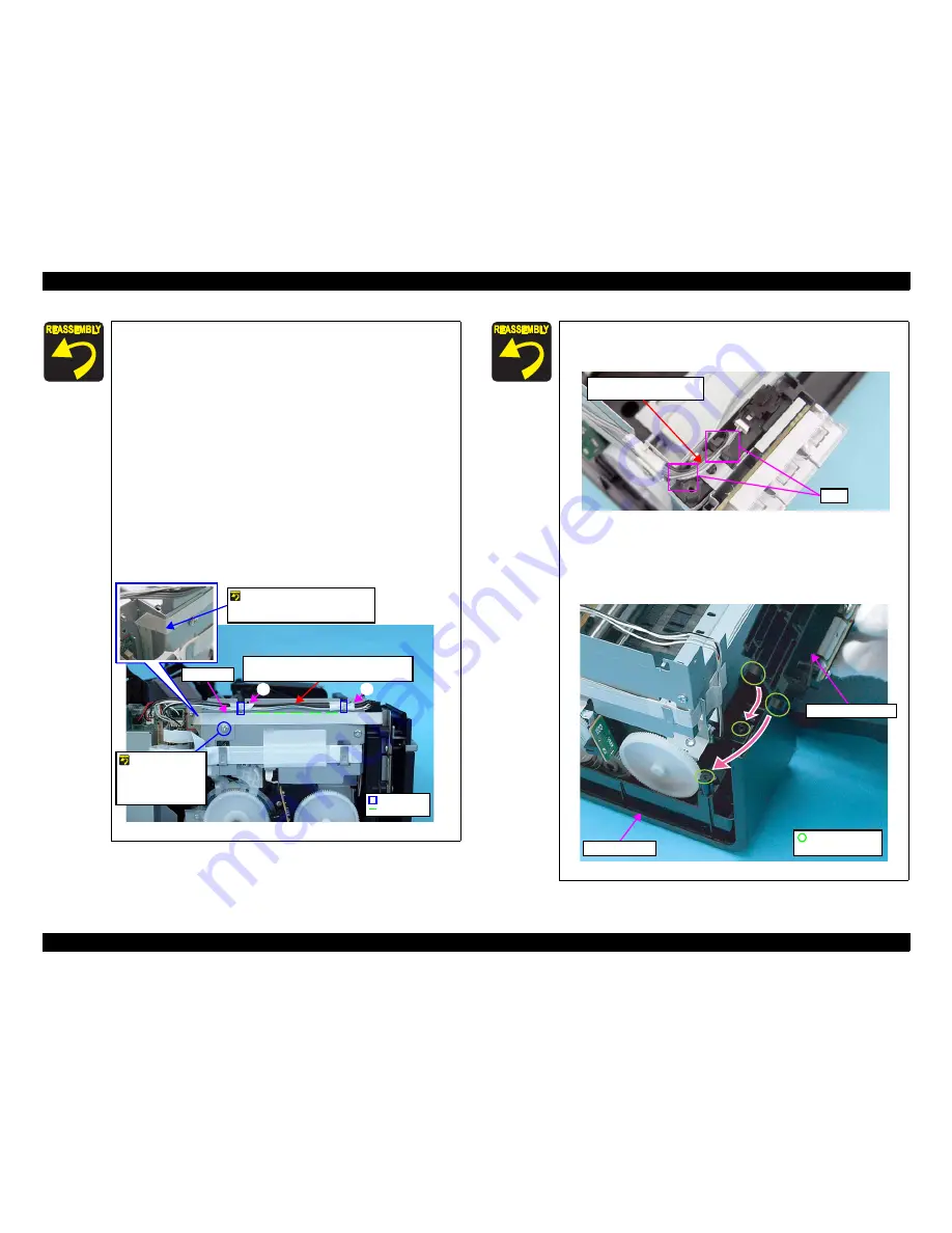
When routing the FFCs and cables, follow the procedures
below referring to
Fig.4-117
.
1. Route the Panel FFC aligning its upper edge with the
reference line marked on the Cable Holder Frame, and
secure the FFC with double-sided tape.
2. Attach the acetate tape C along with the edge of the Cable
Holder Frame to secure the Panel FFC and Head FFC.
3. Tie the two cables together using two pieces of acetate tape
(20 mm each) so that the two tape positions come to the two
hooks of the Cable Holder Frame respectively. The cables
orientation must be as follows;
CDR cable: faces its black side upward
Cover Open Sensor cable: faces its gray side upward
4. Route the cables through the two hooks of the Cable Holder
Frame aligning the center of the tapes with the hooks.
Figure 4-117. Routing the Cables
Upper Side : CDR Sensor Cable
Lower Side : Cover Open Sensor Cable
Hook
A
B
Ref. Line
Do not route the
Panel FFC over
the screw of the
Cable Holder
Frame.
Fold the Panel FFC along the
corner of the Upper Shield
Plate M/B.
Panel FFC
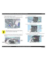
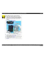
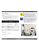
As shown in
Fig.4-118
, route the CDR Sensor Cable and Cover
Open Sensor Cable through the gap between the two ribs of
the Open Sensor Holder.
Figure 4-118. Installing the Panel Assy (1)
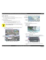
As shown in
Fig.4-116 (p.99)
and
Fig.4-119
, match the
positioning holes of the Open Sensor Holder with the guide
pins of the Lower Housing, and secure the Open Sensor Holder
with the tab.
Figure 4-119. Installing the Panel Assy (2)
Cover Open Sensor Cable
CDR Sensor Cable
Ribs
Lower Housing
Open Sensor Holder
Positioning Hole
and Guide Pin
Summary of Contents for 50 - Artisan 50 - Printer
Page 8: ...Confidential C H A P T E R 1 PRODUCTDESCRIPTION ...
Page 22: ...Confidential C H A P T E R 2 OPERATINGPRINCIPLES ...
Page 29: ...Confidential C H A P T E R 3 TROUBLESHOOTING ...
Page 52: ...Confidential C H A P T E R 4 DISASSEMBLY ASSEMBLY ...
Page 103: ...Confidential C H A P T E R 5 ADJUSTMENT ...
Page 120: ...Confidential C H A P T E R 6 MAINTENANCE ...


