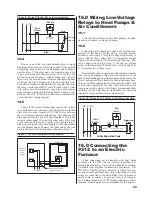
Figure 8: Typical Clothes Dryer Interconnection
14.4
Remove one of the two wires from the dryer’s circuit
breaker and wire-nut (cap) this wire so that it will not short
to anything. Turn on dryer’s circuit breaker and attempt to
start the dryer. If the dryer starts, the detached wire is the
correct wire to attach to the power relay. To verify this, turn
off the dryer and the dryer’s circuit breaker and reattach
this wire to the circuit breaker. Remove the opposite phase
wire from the circuit breaker the wire-nut (cap) this wire.
Turn circuit breaker on and start the dryer again. This time
the dryer’s motor should NOT start. If it does (dryer starts
with either wire disconnected), your dryer may require
some internal wiring modifi cations before it can be con-
nected to the 9312. To do this, contact dryer manufacturer
or consult dryer wiring diagram.
14.5
Turn off the circuit breaker and remove the correct
wire. With the correct wire removed, the dryer motor should
start. Run two short lengths of #10 AWG wire between
the circuit breaker panel and the Relay Unit. Wire-nut the
disconnected wire to one of the short lengths of wire in the
circuit breaker panel. Wire-nut the other end of this wire
to one red lead of the relay’s contact. Wire-nut the relay’s
other red lead to the other short length of wire that returns
into the breaker panel. Connect the other end of the wire
back to the dryer’s circuit breaker as shown in Figure 9.
Figure 9: Dryer Interconnection Schematic
24
15.0 Wiring Low-Voltage
Relays to Heat Pumps &
Air Conditioners
15.1
Turn off all circuit breakers for heat pumps, air condi-
tioners, air handlers, or electric furnaces.
15.2
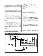
Connecting air conditioners and/or heat pump com-
pressors to the Energy Sentry unit is normally accom-
plished by inserting a 3 Amp low voltage signal relay in
series with the low voltage 24 VAC thermostat control
loop as shown in Figure 10. (Generalized Drawing). This
can be done in one of two ways: 1) Use the low voltage
relays on the Data/Link PC Board for Circuits #2 and #3 or
2) Use remote low voltage relays.
Normally the relay is inserted in the common (usually
red) wire. In heat pumps, this allows the compressor to be
shed in both heating and cooling modes and also causes the
blower and any auxiliary heat to be shed at the same time.
In the event that breaking the red wire is incompatible with
an electronic thermostat, the relay will be inserted in the
compressor relay (yellow). It is strongly recommended that
auxiliary electric strip heat in air handlers be controlled
separately using remote power or signal relays.
Figure 10: Typical Low Voltage Load Interconnection
16.0 Connecting the
9312 to an Electric
Furnace
When connecting an air handler with heat strips
or furnace to the 9312, the most effective method is to
install a Remote Relay Unit at the air handler or furnace.
(Available from Brayden Automation Corporation - P/N
FG9291A). This Relay Unit contains 2 to 6 relays for con-
nection to each individual heat strip in the furnace. These
relays are connected to the Main Relay Unit by means of
paired cable, normally one pair per relay. For example,
for 4 remote relays, an #18 AWG eight conductor cable is
required. Twisted pairs are recommended for this applica-
120V
30A Relay
Dryer
Circuit
Breaker
Disconnect here
and insert relay
120V N
Dryer
M
Heating
Element
120V
Pilot
Relay
Compressor
Relay
Circuit
Breaker
120V N
Air Conditioner/Heat Pump
Disconnect thermostat loop
here and insert relay
24VAC
Thermostat
Relay Unit
Relay
Breaker
Breaker
Panel/
Load
Center
To Dryer
Break here and insert
relay in series
Neutral

