3.0 Pre-Installation
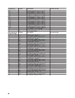
System Check List
3.1 Parts Check
Check package contents to ensure it contains the fol-
lowing parts:
Quantity
Part Number
Description
1
FG9341A
9312 Control/Display Unit
2
8420-3028
200 Amp
Current Transformer
or
8420-3029
400 Amp
Current Transformer
1
Relay Unit: 1 of 2 types
FG9302A-
XXXIXXX
Surface Mount Indoor
NEMA1
or
FG9302A-
XXXRXXX
Rain Tight Outdoor NEMA
3R
* For an expanded system (32 control points) 2 Relay
Units are required
4
9000-02101
Control/Display Unit
Mounting Clips
4
2520-1001
Control/Display Unit
Mounting Screws
1
09000-67102
Control/Display Unit
Mounting Template
1
09312-
94100A
Owner’s/Installation
Manual
Note:
Digits marked with “X” may vary depending with
the number and type of relays, system size, type of enclo-
sure, alarm, and current transformer options.
Note:
Notify your Energy Sentry dealer if any parts are
missing.
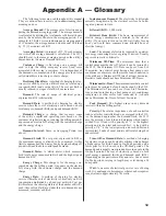
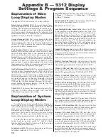
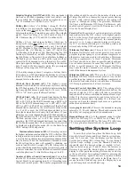
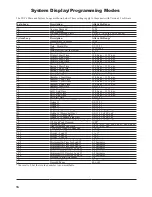
3.2 System Overview
The Energy Sentry 9312 Demand Management System
consists of three general pieces. They are: the Control/
Display (C/D) Unit, the Relay Unit, and the Current Trans-
formers. Figure 3 shows the General System Confi guration.
The C/D Unit mounts inside the home, usually in a general
living area such as the kitchen, hallway, or family room.
The Relay Unit mounts next to the circuit breaker panel.
The Current Transformers mount in the circuit breaker
panel around the main incoming feeder cables.
Installation Manual
17
1.0 Introduction
This manual contains instructions for the installation,
checkout, and programming of the Energy Sentry 9312
Demand Management System. In order to ensure proper
installation and warranty coverage, please read this manual
thoroughly before proceeding with the installation.
Note:
All wiring must be installed in accordance with
national and local electrical codes.
Important:
If the 9312 is to be connected to a heat
pump compressor or air conditioning compressor, please
refer to Appendix B for Minimum On/Off-Times.
2.0 Tools & Materials
Required
2.1 Tools Required
• Flat blade type screwdriver
• Phillips head screwdriver
• Drywall Knife
• Standard crimping tool (needed if optional
crimp-on spade terminals are used)
• Amp-Clamp Current Sensor (if available)
• Digital Volt Meter (required for trouble
shooting only)
2.2 Materials Required
(not provided)
• Four 1/4” x 1” lag bolts and/or appropriate hard-
ware for mounting Relay Unit.
• 15 Amp single pole circuit breaker for the 9312’s
120 VAC Power Supply.
• Suffi cient length of 4 Conductor Control Cable
-Energy Sentry P/N - 0715-0009, or Belden #9156 or
equivalent. This cable has 4-#18 AWG Conductors, 300V
rated. Do not use thermostat wire as it may cause the 9312
to read power incorrectly. Use of thermostat wire may
void warranty.
• Suffi cient length of appropriate hookup wire
(#14 AWG) to connect 120 volt power and ground from
the circuit breaker panel to Relay Unit.
• Suffi cient conduit, #10 AWG or #12 AWG
wire (depending on load size), and associated hardware
to connect the circuit breaker panel to Relay Unit (if
required).

