25
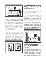
tion for convenience in identifying pairs. Relay connector
pigtails should be connected in the Main Relay Unit to the
multi-conductor cable. At the Remote Relay Unit, relay
leads are wire-nutted to the multi-conductor cable as show
in Figure 11.
16.1
Determine the staging sequence of the electric furnace.
For example, many furnaces have 3 stages of heat. Stages
#1 and #2 often consist of two 5 KW heating elements and
Stage #3 has another 5 KW heating element.
16.2
The heating elements of Stage #1, Heat 1A and Heat
1B, are wired to Relays #2 and #4. The heating elements
of Stage #2, 2A and 2B, are wired to Relays #5 and #6.
Finally, the heating element of Stage #3 is wired to Relay
#7. The dryer would be wired to Relay #1 and water heater
to Relay #3. See Section 12.1.2 for an example.
16.3
Run the multi-conductor cable from the Main Relay
Unit to the Remote Relay Unit. Use the relay connector
pigtails (P/N 09000-65001) to connect each conductor pair
to the relay outputs plugs in the Main Relay Unit. In the
Remote Relay Unit, wire-nut the opposite end of these
conductors to the relay’s coil terminals. Make sure the
color code is observed. Orange wire of each relay should
go back to the top pin of each 2-pin relay output jack.
16.4
Wire the remaining relays similar to the fi rst making
sure that each relay is connected with a pair of wires.
DO
NOT COMMON ANY WIRES TOGETHER
17.0 System Checkout
17.1 Prior to Test:
a. Turn off ALL circuit breakers in the circuit breaker
panel.
b. Turn on thermostats/switches for controlled loads.
17.2 Initial Operation Test:
a.
Ensure all circuit breakers in the circuit breaker panel
are off.
b. Turn on the 9312 circuit breaker.
c.
Control/Display Unit should turn on, beep once, and
light up with “id” showing in the Mode display. If
the unit fails to light up, turn power off immediately.
Check wiring and connections to make sure that the
unit is wired properly. Pay close attention to remote
relay wiring to ensure there are no short circuits.
Power-up the unit again. If problems still arise, call
your Energy Sentry Dealer.
d. All sixteen Circuit On LED indicators should be off
and all relays shed after power-up. The fi rst relay
will turn on about 8 seconds after power-up. Every 1
minute thereafter one circuit indicator light will come
on, except if relays are held open by a Minimum Off-
Time.
17.3 Power Off-Test
a.
Set demand limit to 2 KW according to the instruc-
tions on the front panel of the Control/Display Unit.
RY1
RY3
DRYER
WATER
HEATER
REMOTE RELAY UNIT
RY2
RY4
RY5
RY6
MAIN RELAY UNIT
ELECTRIC FURNACE
2 STAGE
60 AMP
BREAKERS
240 VAC
SUB MAINS
HEAT 2A
HEAT 2B
HEAT 1B
HEAT 1A
Wire nut each
pair to a relay
connector pigtail
Wire nut each
relay to each
cable pair
4 PAIR CABLE
RELAY
WIRE NUTS
ORANGE
WIRE
BLACK
WIRE
(4)
ORANGE
WIRE
BLACK
WIRE
RELAY CONNECTOR
PIGTAIL
CABLE
(See below)
(See below)
(one pair shown)
LOW
VOLTAGE
RELAYS
CT IN
AC#1
AC#2
LOW
VOLTAGE
OUTPUTS
2
3
Figure 11: Electric Furnace/Air Handler Application

