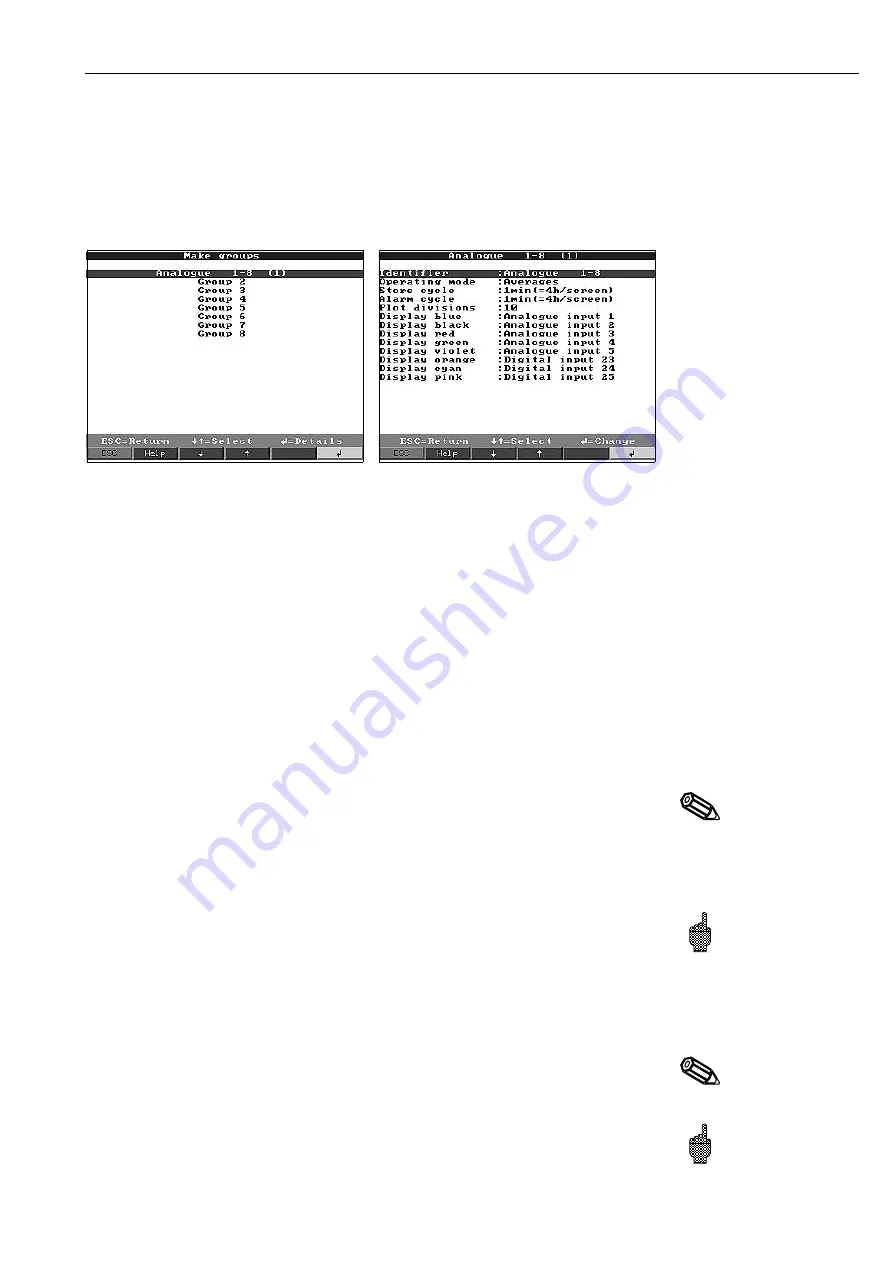
Make groups:
•
Only channels that are allocated to groups are displayed and stored!
Combine analogue and digital channels in such a way that important information can
be called up at the touch of a button (e.g. temperatures, signal in plant 1, ...).
A maximum of 8 channels can be allocated in any group.Up to 8 groups can be
created.
Identifier
Useful identifier for the signals allocated to this group, e.g. temperatures, quantities,
plant 1, ...
Operating mode
Shows how the measured values are to be displayed and stored.
“Instantaneous values”: The instantaneous values are stored at the required time.
“Average values”: The average value since the last store time is calculated and
stored.
Example using a store cycle of 1 minute: the mathematic average is calculated from
60 values, one second cycle, and then stored.
“Min/max. curve”: The minimum and maximum values since the last store are
calculated and then stored.
Example using a store cycle of 1 minute: the smallest and largest value that occurred
from 60 values, second cycle, are analysed. These are displayed on screen
connected by a straight line. They are also stored. The digital display always
indicates the actual instantaneous value (updated every second).
Hint:
In this mode only 4 channels can be allocated to each group.
Store cycle
Time for the measured value store cycle = cycle for display update in normal
operation (no alarm set point infringement or alarm set points are not being
monitored). This then gives the visible area for the graphic plot on the screen (see
values in brackets).
Attention:
the shorter the store cycle the more memory space is required (the time
available gets shorter).
Hint: In order to have long times available in the memory select long store cycles
when operating under “Operation mode” “Averages” or “Min/max. values”. This
means that longer times can be seen in the display.
Alarm cycle
Time for measured value store cycle = cycle for display update in alarm condition (set
point active). This can be stored and displayed with a higher resolution.
Hint:
At least one analogue signal (or PROFIBUS measurement point) in the group
must be in an alarm condition and “Store limit value” must be set to “Alarm cycle”
(see “Analogue inputs - alarm set point” or “Mathematics channels - limits”). Then all
channels in the group are stored in the preset alarm cycle.
Attention:
the shorter the alarm cycle the higher the memory requirement (the time
available gets shorter).
5. Set-up unit
85


