Art.-Nr./Art. No./Réf./N° art/N° art.: 9010003B01M
Version/Version/Version/Versione/Versión: 1.1
Datum/Date/Date/Data/Fecha: 04.04.2016 4/19
153MSK...
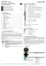
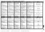
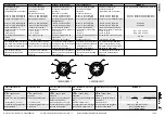
Type key safety sensor
Type key actuator
2
Designated use
In combination with the elobau safety control units or similar safety controllers,
the safety sensors and actuator 153MBK... are exclusively used to monitor
moving, isolating safety devices.
The safety control units (or similar) detailed in chapter 7 “Function” on page 4
achieve PDF-M / PDF-S-classification according to EN 60947-5-3 in combin-
ation with the safety sensors and actuators.
The overall control concept in which the safety sensor is incorporated, must be
validated, for example, according to EN ISO 13849-2.
3
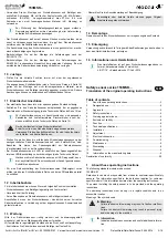
Approvals
4
Safety instructions
5
Warning against misuse
6
Exclusion of liability
No liability shall be accepted for any damage or operational faults caused by a
failure to observe these operating instructions. All further liability of the
manufacturer is excluded in the case of damage caused by the use of
replacement and accessory parts that have not been authorized by the
manufacturer.
No unauthorized repairs, conversions or modifications are permitted for reasons
of safety and the manufacturer shall not be liable for any damage resulting
therefrom.
7
Function
A coded magnetic safety sensor with a non-contact activation through a coded
actuator.
Type 3; for side reinforced variants the requirements contained in
EN ISO 14119 are to be observed
Type 4; low coding level according to EN ISO 14119
An elobau safety control unit or similar safety processing unit / safety controller
analyses the switching state of the safety sensor. PDF-M and PDF-S is
achieved only in combination with the elobau safety control units listed below or
comparable safety control units / safety controllers.
The safety sensors are suitable for the following elobau safety control units:
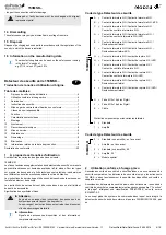
153MSK.0.1.
A =
N.O. contact / N.O. contact
B =
N.O. contact / N.O. contact / LED
C =
N.O. contact / N.O. contact / control contact N.O. contact
D =
N.O. contact / N.O. contact / control contact N.O. contact /
LED
E =
N.O. contact / N.O. contact / lateral control
F
=
N.O. contact / N.O. contact / lateral control / LED
G =
N.O. contact / N.C. contact
H =
N.O. contact / N.C. contact / LED
I
=
N.O. contact / N.C. contact / control contact N.O. contact
J
=
N.O. contact / N.C. contact / control contact N.O. contact /
LED
K =
N.O. contact / N.C. contact / lateral control
L
=
N.O. contact / N.C. contact / LED / lateral control
H =
Plug M12x1 4-pole Pigtail
J
=
Plug M12x1 8-pole Pigtail
K =
Cable
Distinction only for lateral variants
0
=
standard
1
=
reinforced
153MBK.01
0
=
standard (non-reinforced); end face
1
=
reinforced, end face
2
=
standard (non-reinforced); 90°
3
=
reinforced, 90°
4
=
special design
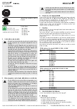
[INDUSTRIAL CONTROL SWITCH]
E336137
(Tested according to ECOLAB
standard)
Test media:
- Distilled water
- P3-topax 66
- P3-topactive 200
- P3-topax 52
- P3-topax 990
- Ensure that the safety sensors are only mounted and put into
operation by specially-trained and authorised personnel.
- Only install and put the device into operation once you have
read and understood the operating instructions and are familiar
with the applicable regulations on occupational safety and
accident prevention.
- The safety sensor may only be activated by a correctly mounted
actuator on the safety device. Actuation by a spare actuator that
is not mounted to the safety device is prohibited.
- The safety sensors may only be operated in a perfect function-
ing condition.
- Ensure that the safety sensors are exclusively used to protect
against risks.
- Ensure that all of the valid safety regulations for the respective
machine are complied with.
- Ensure that all of the valid laws and directives are complied with.
- Connecting safety sensors in series can, under certain
circumstances, reduce their performance level according to
EN ISO 13849-1 standards due to a lower detection of errors.
- There are no known residual risks, if all of the information
contained in these operating instructions is complied with.
- In case of incorrect or unintended use or manipulation, the use
of the safety sensors does not exclude risks to persons or
damage to machine or system components.
Please also observe the relevant information stipulated in
EN ISO 14119.
- Please ensure that when using safety control units that have not
been supplied by elobau, no current or voltage peaks which are
higher than the specified electrical data of the safety sensor are
generated by these devices. Current or voltage peaks are
produced, for example, by capacitive or inductive loads.
- The safety sensor is not short-circuit proof.
- An exceeding of the electrical data of the safety sensor (e.g. in
the event of incorrect wiring or short-circuits) may cause
irreparable damage to the sensor.
- The safety sensor may only be activated in the approved control
options (see Technical specifications).
Non-compliance with this information may result in reduced
service life of the safety sensor.

