background image


Ecos

aire

®


 EN Series Precision Air Conditioner              Owners Manual

Installation                                 Wiring                            Control Wiring   

43


Ecos

aire

®


July   2007

Data subject to change without notice.

J11

J12

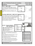
Expansion Memory

J9

J10

C1

Rx

-/

T

x-

NO1

Rx

+

/T

x+

NO2

GND

NO

3

C1

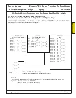
Optional Remote Display

Note: Cables may be supplied , depending on options.

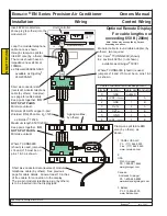
The communication system between the controller and the remote display (if any) is based on ANSI/IEEE RS-

485.  For best results, proper RS-485 wiring and splicing methods should be used.  These include, but are not lim-
ited to the use of shielded RS-485 cable (Z0=120

, e.g. Belden 7202A), the use of connectors rated for RS-485,

minimized untwist of conductors, etc.

In some cases, shorter lengths of cable may allow approximations to RS-485 methods.  These methods are

shown on the folowing pages.  Methods for longer cables will work for shorter cables also.

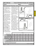
For cable lengths not exceeding 160 ft (50m) -

3-gang wall box (by others)

At each end of the cable, loop the 
modular telephone cable once as shown
through clamp-on split ferrite EMI cores
(by  others).  The cores should have an
impedance near 240

at 100MHz.

ex: Steward 28A0640-0A0

available as Digi-Key1 240-2065-ND

Allow at least 10 inches of free cable for
connection to the display.

Insert 6P6C modular telephone
plug (by others) into the modular
port.  

electrical enclosure
of unit

Six-pin modular telephone plug
(by others) to be inserted into dis-
play jack.

1.  Digi-Key Corp.

1-800-344-4539
www.digikey.com

INST

ALLA

TION

Note:

Depending on options, cables may

be supplied by Dectron.

For cable lengths not exceeding 160 ft.

(50m), it is possible to use a six-conductor
data (reversed) modular telephone cable
(by others).  See next page for cable
details.

Communications between the unit and

the remote display can be disrupted by
external electrical noise.  Such noise can
be produced by variable speed motor
drives, light dimmers, electric discharge
lighting, and other non-linear electrical
loads.   Where this is the case, use fer-
rites as described at right.

Summary of Contents for EN Series

Page 1: ......

Page 2: ...important instructions in operating and maintaining your Ecosaire system Please read the entire manual carefully and if you have any questions con tact your local Ecosaire representative Your warranty is valid only if conditions explained in this manual are met To the Installer This manual contains vital instructions for installing and starting up the Ecosaire system Please read the entire manual ...

Page 3: ...y Registration 69 Warranty 71 Operation Contents 73 Maintenance Schedule 74 Maintenance Record 76 Maintenance Tasks 79 Logical Flow Charts 84 Supervisaire Controller Interface 85 Password 86 Enable Disable 87 Clock 88 Set Point Change 89 Alarms 91 Alarm History 92 Component Run Times 93 Supervisaire Diagnostics 94 Refrigerant Charges 96 Sensor Response Curves 101 All Ecosaire equipment offers maxi...

Page 4: ... Ecosaire Precision Environmental Control sys tems Individual Ecosaire units can be connected on a built in local area network together with a supervisory panel complete with a backlit graph ics display for robust redundant environment control At the same time the network can be connected to a personal computer supervisory system or to a BACNETTM or MOD BUSTM network The LCD panel is large and eas...

Page 5: ... evaporator all refrigeration components are located out of the air stream System reliability is enhanced with multiple direct driven independent fan assemblies which maintain 66 to 50 of the airflow in the event of a fan failure The direct drive feature eliminates the need for belt and pulleys and offers reduced drive losses also negating the need for time consuming drive maintenance Multiple fan...

Page 6: ...tional flood back controls are available for either 30 F 34 C or 40 F 40 C operation See Installation Piping for details Water Cooled Direct Expansion The Ecosaire unit operates its refrigeration system as needed to control room conditions Heat is transported via refrigerant vapor flow to an internal water cooled condenser The refrigerant liquifies in the condenser and re circulates Water is pumpe...

Page 7: ...or heat exchanger The outdoor heat exchanger has multiple direct drive propeller fans and is built with aluminum body panels and copper tubes with aluminum fins A factory wired control box is supplied for field connection The TEFC NEMA rated pump mounts directly to the glycol cooler subbase Pre wired fan and pump control boxes are provided Glycol coolers are available for the following ambient con...

Page 8: ...ed When the outdoor temperature is below 60 F 16 C the Ecosaire unit operates its refrigeration system to move heat into a flow of glycol Refrigeration condensing pressure is controlled by pressure con trolled throttling valves Heat is transferred via pumped glycol fluid flow to an outdoor heat exchanger Whenever refrigeration is not needed the glycol flow is diverted to internal air heat exchange...

Page 9: ...uildings chilled water by others DESCRIPTION service isolation valves by others If the flow rate or temperature of the chilled water becomes inadequate for proper operation the unit will automatically change to Air Cooled Direct Expansion Air cooled condensers are available for the following conditions Design Standard Low Ambient Temp min max F min max F 95 F 35 C 0 105 F 17 41 C 40 105 F 40 41 C ...

Page 10: ... The unit is rated for use with 45 F 7 2 C chilled water For flow rates and other details see Installation Piping If the flow rate or temperature of the chilled water becomes inadequate for proper operation the unit will automatically change to Glycol Cooled Direct Expansion Glycol coolers are available for the following ambient conditions Design Temp 95 F 35 C 100 F 37 8 C 105 F 40 6 C Remote Gly...

Page 11: ...re of the chilled water becomes inadequate for proper operation the unit will automatical ly change to Water Cooled Direct Expansion The temperature of the cooling water entering the unit must be between 65 F 18 3 C and 85 F 29 4 Contact the factory for lower temperatures chilled water or other fluid by others cooling water or other fluid by others DESCRIPTION E X A M P L E A p p e a r a n c e l o...

Page 12: ... to change without notice Product Description Air Flow Options DESCRIPTION Airflow Pattern U Airflow Pattern W Airflow Pattern R Airflow Pattern S Airflow Pattern N Airflow Pattern M E X A M P L E S A p p e a r a n c e l o c a t i o n a n d q u a n t i t y o f c o m p o n e n t s m a y v a r y ...

Page 13: ... Q 3 way Water Modul Valve D2 D3 F G W R Water Flow Switch S Non fused Disconnect T Fused Disconnect U Circuit Breaker V Shell Tube Heat Exchanger X Adjustable Floor Stand Y Alarm Buzzer Silence Push Button Z Control Type 0 No Microprocessor S Standard Microprocessor Wall Thermostat T Filter Section F 30 G 65 Humidifier 0 None H 17lb hr 8kg h Electrode Steam Humidifier Live Steam Steamgrid L Heati...

Page 14: ...ANT DESIGN PRESSURE PRECISION CONTROL AIR CONDITIONER Before calling for assistance be sure to have the model serial and tag numbers available for the service department Be sure the voltage and current ratings of the unit branch circuit match these values This is important compressor electrical information for those units so equipped This is important blower electrical information This is importan...

Page 15: ...om air to escape into the ceiling plenum Because of the small number of per sonnel in a typical computer site out door air should be reduced to less than 5 of the total circulated air If outdoor air is introduced it must be filtered The effect of bringing in outdoor air must be added to the cooling and dehumidifica tion loads Measures should be taken to prevent dirt and dust from affecting equipme...

Page 16: ...st be covered with the shipping carton or plastic film in order to keep the filters and internal components clean Do not allow water plaster con crete dusts or other foreign materi als to enter any open pipes or tubes Do not operate the unit or other wise allow construction dust to enter the unit The resulting damage is not covered by the Ecosaire warranty DX units Cooling Type A The maximum one w...

Page 17: ...ey might be accidentally touched Lifting holes are provided at the top of the support legs The nuts and bolts securing the unit to the crate are used to mount the lower support leg sections and horizontal braces to the unit Assemble the outdoor unit accord ing to the instructions provided with it The outdoor heat exchanger should not be enclosed within a solid fence or wall since such structures p...

Page 18: ...ided Areas subject to public access should be avoid ed Locate outdoor units in an area of clean air away from steam hot air or fume exhausts Units installed on roofs should be mounted on steel supports in accordance with local codes A concrete pad is sufficient for ground installations Provide clearances as shown below Insulate hot gas tubes where they might be accidentally touched Assemble the ou...

Page 19: ...er static pressures result in higher power requirements and increased noise The maxi mum external static pressure is specified for each unit Static pressures higher than specified may reduce air flow below the mini mum acceptable value Select grilles registers and dif fusers for low static pressure loss required throw and specified air flow Choose hardware resistant to deterioration due to chemica...

Page 20: ...ving the ECOSaire There should be no elbows transitions offsets duct heaters or other flow interruptions closer that 5 X the width of the blower Some installations may have external duct heaters by others To prevent heater failures and hot spots locate the heater at least 5 X the duct width away from the blower or any air flow interruptions such as elbows and transitions Supply Duct Duct Isolator ...

Page 21: ...f the window RIGHT Vanes and straight length allow air to flow evenly RIGHT Vanes and straight length allow air to flow evenly RIGHT Air can follow this transition RIGHT Sufficient straight length allows proper air flow Flexible duct connection absorbs vibration 2 5 W or more W Turning Vanes Turning Vanes RETURN DUCT SUPPLY DUCT 30 or more 20 or less 5W or more W RIGHT Dry air reaches all the wind...

Page 22: ...ioner Owners Manual 22 Ecosaire July 2009 Data subject to change without notice For installation connections for the humidifier please refer to the Carel humidifier manual included with this manual Installation Piping Humidifier INSTALLATION ...

Page 23: ... downward at least 1 4 per foot 2 cm per meter Deliver the condensate to a suit able point Check local codes for allowable procedures Fill P trap To prevent air from being drawn through the condensate drain pipe the P trap must be filled with water before starting the unit blowers Failure to do this will cause the drain pan to overflow during operation Condensate pump Condensate pumps are standard...

Page 24: ...nge without notice If pressure testing be sure to isolate the compressor from high pressure To System To System Note below the operation of rotalock service valves as found on Ecosaire compressors and receivers INSTALLATION E X A M P L E A p p e a r a n c e l o c a t i o n a n d q u a n t i t y o f c o m p o n e n t s m a y v a r y ...

Page 25: ...to property damage and or personal injury Locate the refrigerant liquid line solenoid valves usually two per circuit Some units may be equipped with manual lift valves Where this is the case 1 Using two wrenches remove the manual stem covers 2 Turn the manual stems clockwise to open the valves stem cover manual stem INSTALLATION E X A M P L E A p p e a r a n c e l o c a t i o n a n d q u a n t i t...

Page 26: ...uation stage since the filter drier will be exposed to atmosphere Close the rotalock valves and remove the reclaim equipment Remove the condenser tube stub caps with heat or with a tube cutter To prevent the introduction of foreign materials into the refrigeration system do not use a saw Remote condenser connections Use care to prevent cross connections INSTALLATION E X A M P L E A p p e a r a n c...

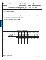
Page 27: ... 1 3 8 1 3 8 1 3 8 1 5 8 1 5 8 1 1 8 1 1 8 1 1 8 1 1 8 1 1 8 1 1 8 1 1 8 1 1 8 1 3 8 1 3 8 1 3 8 1 3 8 1 3 8 1 5 8 1 5 8 1 5 8 1 1 8 1 1 8 1 1 8 1 1 8 1 1 8 1 1 8 1 1 8 1 1 8 Air Cooled Direct Expansion and Air Cooled DualCool Units Only Equivalent length of tube ft one way R 410a condenser connecting tube sizes inches O D EN 027A Gas Liq Gas Liq Gas Liq Gas Liq Gas Liq Gas Liq Gas Liq Gas Liq EN ...

Page 28: ...RTANT Never allow liquid water to enter the remote condenser or the tubes connecting it Water must be removed from the remote con denser and the tubes that connect it to the Ecosaire Evacuation will take much longer if liquid water is present Installation Piping Refrigerant Tube Air Cooled Direct Expansion and Air Cooled DualCool Units Only Total length of tube not to exceed 100 ft one way Horizon...

Page 29: ...EN 051 4 8 ______ EN 068 7 4 ______ EN 079 7 4 ______ EN 087 7 4 ______ EN 102 9 9 ______ Liquid Line R 410a lb per circuit O D lb length in ft ft 5 8 0 126 X _____ ______lbs 3 4 0 185 X _____ ______lbs 7 8 0 259 X _____ ______lbs 1 1 8 0 441 X _____ ______lbs Condenser lb KMG041 21 _____ KMG051 31 _____ KMG061 33 _____ KMG075 48 _____ KMG085 66 _____ KVG085 38 _____ KVG096 38 _____ KVG106 57 ____...

Page 30: ...on oil 1 Note the compressor model from the compressor nameplate If it is not a Copeland brand please contact Ecosaire 2 Note the type of oil to be added from the compressor nameplate Copy this type into BOX C on page 32 3 Add 1 fluid ounce of oil for every 5 pounds of refrigerant over 20 pounds BOX A 20 lb BOX A1 5 lb Prepare to add this many ounces of the type of oil specified on the compressor ...

Page 31: ...Owners Manual Ecosaire EN Series Precision Air Conditioner Installation Ecosaire July 2009 31 Data subject to change without notice This page intentionally left blank ...

Page 32: ...rigeration service gauges an electronic micron level vacuum gauge and a vacuum pump as shown below Use core removal adapters to remove the cores from Schraeder type access valves To insure a correct vacuum reading install the electronic vacuum gauge far away from the vacuum pump or use a reliable vacuum valve to isolate the gauge and system from the pump while reading the vacuum Colder ambient tem...

Page 33: ...ice Piping Installation Each circuit of an Ecosaire unit may have two liquid line solenoid valves Release the liquid line solenoid valve from the locked open position by turning the manual stem counter clockwise all the way Replace and tighten the stem cap INSTALLATION E X A M P L E A p p e a r a n c e l o c a t i o n a n d q u a n t i t y o f c o m p o n e n t s m a y v a r y ...

Page 34: ...ater flow is essential All pumps cooling towers fans etc involved in cooling the water must be enabled whenever the Ecosaire unit is operational Do not allow a timer or other device to inhibit operation at any time the Ecosaire unit is operational IMPORTANT Cooling water must be protected from freezing if the water flow could be interrupted during low ambient temperatures Water Pressure Switch The...

Page 35: ...nions according to the fac tory piping diagrams Install a fill port at the highest point of the system To insure proper glycol water ratio never use automatic fillers Where copper tubing use Type L only is used joints should be hard soldered The inlet header is con nected to the top of the condensers and the outlet header to the bottom FreeCool units include head pressure controlled glycol regulat...

Page 36: ...t and outlet headers should be carefully loosened to permit air to escape Do not remove the plugs since they can be difficult to replace once glycol reaches the port The core of the access valve on the glycol cooler inlet header must be held open or temporarily removed Pour the glycol mixture into the system fill port until full Ecosaire EN Series Precision Air Conditioner Owners Manual Data subje...

Page 37: ...Ecosaire July 2009 37 Owners Manual Ecosaire EN Series Precision Air Conditioner Data subject to change without notice INSTALLATION This page intentionally left blank ...

Page 38: ...se properly sized wire Refer to the unit nameplate for electrical ratings Size wires according to applicable codes with allowance for voltage drops Unit terminal voltage should be nominal 10 under all conditions includ ing compressor starting Insure phase rotation All the motors in the unit are con nected for the same phase rota tion Be sure the phase rotation is correct before completing the inst...

Page 39: ...ectric power to the branch circuit connected to terminals L1 L2 and L3 3 If the fans do not blow air in the proper direction see below a disconnect electric power following all safety precautions b a qualified person should interchange any two branch circuit conductors DO NOT CHANGE ANY FACTORY WIRES c return to step 2 4 If the fans blow air in the proper direction see below then a disconnect elec...

Page 40: ...e an internal Ecosaire power source The condenser control wire size must be selected to allow for contactor coil inrush currents See the chart at right Alternatively a pilot relay by others may be installed In some cases temperature switches inside the remote condenser may have to be adjusted wire length Number of fan contactors ft 1 2 3 4 5 6 10 20 20 20 20 20 18 20 20 20 20 20 18 14 30 20 20 20 ...

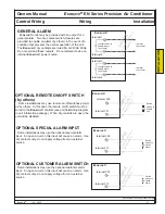
Page 41: ... on off switches provid ed by others In this case the remote on off switch must be wired to the Ecosaire controls see unit field wiring diagram in unit information package When dry contacts are open the unit will be disabled Switch closes to enable unit terminal 300 terminal 301 S A M P L E U s e t e r m i n a l n u m b e r s i n u n i t w i r i n g d i a g r a m OPTIONAL SPECIAL ALARM INPUT Some ...

Page 42: ...Ecosaire EN Series Precision Air Conditioner Owners Manual Installation Wiring Control Wiring 42 Ecosaire July 2009 Data subject to change without notice INSTALLATION This page intentionally left blank ...

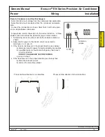
Page 43: ... gang wall box by others At each end of the cable loop the modular telephone cable once as shown through clamp on split ferrite EMI cores by others The cores should have an impedance near 240Ω at 100MHz ex Steward 28A0640 0A0 available as Digi Key1 240 2065 ND Allow at least 10 inches of free cable for connection to the display Insert 6P6C modular telephone plug by others into the modular port ele...

Page 44: ...OW BLUE WHITE BLACK RED GREEN YELLOW BLUE WHITE BLACK RED GREEN YELLOW BLUE WHITE BLACK RED GREEN YELLOW BLUE Assembling data reversed modular telephone cable Note that the lock tabs of the plugs are on opposite sides of the cable Colors are for example only colors may vary by cable vendor Optional Remote Display TOP VIEW END VIEW END VIEW END VIEW END VIEW SIDE VIEW INSTALLATION ...

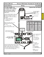
Page 45: ... modular telephone plug by others is to be inserted into the display jack Insert 6P6C modular tele phone plug by others into the modular port Unit Controller Modular cable to round cable adapter by others two required Ex Carel1 TCONN6J000 shown Ex Leviton 40276 I not shown available as Grainger2 5C381 Where TCONN6000 shown is used jumpers J14 and J15 must be on pins 1 3 as shown Where TCONN6000 sh...

Page 46: ...s See previous page for cable details Allow at least 10 inches of free cable for connection to the display The six pin modular telephone plug by others is to be inserted into the display jack Unit Controller Keep pair together DO NOT SPLIT PAIRS Minimize untwist Insulate shield at this end Do not connect shield to a terminal Keep pair together DO NOT SPLIT PAIRS Minimize untwist 1 CAREL USA LLC Ph...

Page 47: ... the end of the cable thorugh the hole in the sub base as shown Using care to maintain level screw the sub base to the wall box here Connect the cable to the modular telephone jack on the back of the display Screw the display to its sub base here Snap the front cover over the display NOTE If power is applied before the Start up tasks are accomplished the display may show NO LINK This is normal and...

Page 48: ...ubject to change without notice Contents Startup Page Supervisaire 44 Controller Interface 46 Pre Startup Adjustments 48 Airflow 49 Remote Heat Exchanger 59 Pre Startup Checklist 64 Enable Operation 67 Expansion Valve Adjustment Startup Report 69 Warranty Registration 71 Warranty STARTUP ...

Page 49: ...ne set and confirm that the airflow is within 10 of the specified value Airflow must be measured with all access doors closed Airflow is adjusted by changing the variable sheave on the blower motor shaft The airflow rate should be within 10 of the value stated on the submittal forms Some Ecosaire units may have voltage monitors that prevent operation in the event the branch circuit voltage is too ...

Page 50: ...d or outward optional remote condenser Air Cooled Direct Expansion Glycol Cooled Direct Expansion Air Cooled DualCool Glycol Cooled DualCool Units Only HEAT EXCHANGER FAN THERMOSTATS Remote heat exchangers have a minimum number of fans that run whenever the Ecosaire unit is in cooling mode Other fans may be controlled by thermostats sensing outdoor air temperature Where this is the case the thermo...

Page 51: ...Ecosaire EN Series Precision Air Conditioner Owners Manual 46 Ecosaire July 2009 Data subject to change without notice STARTUP This page intentionally left blank ...

Page 52: ... three phase fans confirm that the fans turn in the proper direction to blow air upward If they do not a qualified person should disconnect power from the remote heat exchanger swap any two branch circuit wires and re connect electrical power to the remote heat exchanger Do not move any factory installed wires For Air Cooled Direct Expansion and Air Cooled DualCool units remove the temporary jumpe...

Page 53: ...lpm 408 346 274 230 204 40 9 34 8 107 8 91 3 72 5 60 8 53 8 155 132 408 346 274 230 204 81 4 308 81 4 308 Startup Check Remote Heat Exchanger Operation Glycol Cooled Direct Expansion Glycol Cooled DualCool FreeCool Units Only continued from previous page Check that the glycol solution is flowing at the proper flow rate See table below After the pump s run for a while residual air may be removed Ch...

Page 54: ... compressor rotalock valves are open Locate the refrigerant receiver in the remote condenser Be sure the rotalock valves on the receiver are open by turning the stems counter clockwise Replace the stem caps STARTUP Ecosaire E X A M P L E A p p e a r a n c e l o c a t i o n a n d q u a n t i t y o f c o m p o n e n t s m a y v a r y E X A M P L E A p p e a r a n c e l o c a t i o n a n d q u a n t ...

Page 55: ...Ecosaire EN Series Precision Air Conditioner Owners Manual 50 Ecosaire July 2009 Data subject to change without notice STARTUP This page intentionally left blank ...

Page 56: ...lCool units and FreeCool units be sure that any fluid valves by others are open For Water Cooled Direct Expansion units be sure any water valves by others are open For Glycol Cooled Direct Expansion units be sure any glycol valves by others are open STARTUP Ecosaire Ecosaire Ecosaire E X A M P L E S A p p e a r a n c e l o c a t i o n a n d q u a n t i t y o f c o m p o n e n t s m a y v a r y ...

Page 57: ...ioner Owners Manual 52 Ecosaire July 2009 Data subject to change without notice Humidifier if any Some units may be equipped with electrode type humidifiers Refer to the humidifier manual supplied with this manual Startup Humidifier STARTUP ...

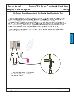
Page 58: ...cess valve while the com pressor is OFF then refrigerant vapor only can be added to the unit through the suction access valve while the compressor is running NEVER ADD LIQUID REFRIGERANT TO THE SUCTION ACCESS VALVE Units with two refrigeration circuits will have two sight glasses and two suction access valves Arrange as below to add refrigerant Close the access panels as far as possible and tempor...

Page 59: ...hes on either side of the temperature sensor Tape the insulation to prevent air flow from changing the temperature reading Locate and identify the refrigerant sight glasses Locate and identify the expansion valves associated with each sight glass Startup Prepare to Adjust Expansion Valves Air Cooled Direct Expansion Water Cooled Direct Expansion Glycol Cooled Direct Expansion Air Cooled DualCool G...

Page 60: ...drain pipe is properly connect ed with a P trap and is free of leaks Confirm that the condensate drain P trap has been filled with water and that the drain works For units with humidifiers con firm that the water supply tube is complete and tested For units requiring a conden sate pump confirm that the pump is operating Make sure copper lines including the capillary tubes at the thermal expansion ...

Page 61: ...rm that all construction dust and debris has been removed from ducts and plenums For glycol cooled and Free Cool units make sure all pipe air vents are closed tightly Remote Heat Exchanger if any Confirm that the heat exchanger is located properly for good airflow see Installation Locate Remote Heat Exchanger Confirm that the voltage applied to the heat exchanger corresponds to that specified on t...

Page 62: ... Password The clock is set at the factory for date and Eastern Time These settings can be changed as below To access Clock Function press Prg and highlight CLOCK as shown To select CLOCK press to view the CLOCK menu To change the clock press repeatedly until the cursor is at the desired value The example is to change the hour Press either or to change the selected value To store the setting press ...

Page 63: ...To store the new value press repeatedly to move the cursor back to the top left corner Startup Pre Startup Adjustments Humidity Set Points field press enter to move to each field Set point Low and High Limit To select the humidity set point press to move the cursor to the set point To change the humidity set point press either the or the button to select the desired humidity The longer the button ...

Page 64: ...tup Adjustments Controller Password Press to access Temperature Set Pts Press to move the cursor to the set point To access the temperature alarm set point screen press twice Press Prg enter the password and press as discussed in Startup Pre start up Adjustments Controller Password The screen will appear as shown The temperature alarms are factory set for High 80oF and Low 60oF If the room tempera...

Page 65: ...hat there is no construction dust in the space ducts or plenums 1 Apply electric power Allow at least 10 hours of crankcase heater operation before enabling a compressor if applicable 2 Do not allow a compressor to run without adequate refrigerant if applicable Press to move the cursor to UNIT ON OFF Press to change STOP to START To store the setting press to return the cursor to the upper left co...

Page 66: ...er Be sure the temperature of the ambient air is less than the rating of the condenser For each refrigeration circuit With the compressor running check that the refrigerant sight glass is full Check the suction pressure and the discharge pressure at the compressor The suction pressure should be above 50 PSI If it is not above 50 PSI stop and determine the cause The discharge pressure should be 250...

Page 67: ...ressure and the discharge pressure at the compressor The suction pressure should be above 50 PSI If it is not above 50 PSI stop and determine the cause The discharge pressure should be 250 PSI 15 PSI If it is not then check that the cooling fluid temperature and flow rate are within specifications Water Cooled Direct Expansion Glycol Cooled Direct Expansion Air Cooled DualCool Glycol Cooled DualCo...

Page 68: ... be needed 3 Read the temperature of the suction tube by the temperature sensor 4 Read the suction pressure NOTE The expansion valves cannot be adjusted if the suction saturation temperature is above 50 F Decrease the room temperature and start over 5 Use the chart below to determine the suction saturation temperature 6 Subtract the suction saturation temperature from the temperature sensor temper...

Page 69: ...eries Precision Air Conditioner Owners Manual 64 Ecosaire July 2009 Data subject to change without notice Startup View Status FOR GLYCOL COOLED AND FREE COOL UNITS ONLY STARTUP This page is left blank intentionally ...

Page 70: ... true Date and time set All alarms cleared ECOSaire Startup Report Warranty Registration Warranty void unless this form is completed and a copy returned to factory within 2 weeks after start up Installation Name Installation Address Ecosaire Representative Model Serial Compressor 1 if any Serial Blower Belt Size Compressor 2 if any Serial Software date Rev Compressor 3 if any Serial Compressor 4 i...

Page 71: ...anty void unless this form is completed and a copy returned to factory within 2 weeks after start up Operational Data NOTE To obtain adequate readings a delay of ten 10 minutes is required after every operation or adjustment 1st stage Dehumidifi cation Only 2nd stage Dehumidifi cation Only Humidi fication Only 1st stage Cooling Only 2nd stage Cooling Only Heating Only Entering Air Temperature F Le...

Page 72: ...y Buyer 9 Seller warrants that the title conveyed under the terms of this Contract shall be good and marketable and that the goods shall be delivered free from any lien encumbrance or security interest whatsoev er 10 Seller warrants that the sale or use of its products will not infringe any United States patent and undertakes to indem nify Buyer against all judgments decrees costs or expenses resu...

Page 73: ...ed to a common carrier licensed public trucker or Buyer or its agent viii any loss or damage caused by failure to install or maintain equipment in accordance with Seller s instructions including without limitation failure to replace filters and belts or clean lubricate or properly calibrate equipment ix consumables such as but not restricted to humidifi er bottles filters fuses refrigerant lubrica...

Page 74: ...ation OPERATION Page 74 Maintenance Schedule 76 Maintenance Record 79 Maintenance Tasks 84 Logical Flow Charts Supervisaire 85 Controller Interface 86 Password 87 Enable Disable 88 Clock 89 Set Point Change 91 Alarms 92 Alarm History 93 Component Run Times Supervisaire 94 Diagnostics 96 Refrigerant Charges 101 Sensor Response Curves ...

Page 75: ...nstructions see Operation Maintenance Humidifier Check that the condensate drain pan s is clean For units so equipped check that the remote heat exchanger is clean Clean any trash or leaves that might interfere with proper airflow Check remote heat exchanger if any fan operation See Operation Maintenance Remote Heat Exchanger Every Six Months For units with mechanical refrigeration check that ther...

Page 76: ...ntenance Record Maintenance Operation Ecosaire July 2009 71 Data subject to change without notice Photostat the next two pages as needed Tape the spine edges of the copies together Post the copies as appropriate to be filled out by maintenance personnel OPERATION ...

Page 77: ...o change without notice No alarms Room temperature Room humidity Air filters clean Humidifier strainer clean Humidifier high water sensor not lit Condensate drain pan clean Remote heat exchanger clean Remote heat exchanger fans OK Sight glass clear Evaporator superheat Electrical terminals tight Internal air heat exchangers clean DATES ...

Page 78: ...Owners Manual Ecosaire EN Series Precision Air Conditioner Maintenance Record Maintenance Operation Ecosaire July 2009 73 Data subject to change without notice DATES ...

Page 79: ...Ecosaire EN Series Precision Air Conditioner Owners Manual 74 Ecosaire July 2009 Data subject to change without notice Operation Maintenance This page intentionally left blank OPERATION ...

Page 80: ...least every month Dirty filters can prevent proper operation and can lead to expensive repairs If filters are dirty replace them with filters of equal per formance If filters are extremely dirty after a month of operation replace them more often OPERATION Airflow Pattern U Airflow Pattern W Airflow Pattern S Airflow Pattern R Airflow Pattern M Airflow Pattern N FILTERS FILTERS FILTERS ...

Page 81: ...protect the heat exchangers from corrosion do not use alkaline or acidic cleaning solution The condenser should not be enclosed within a solid fence or wall since such structures promote recirculation of air If a fence or wall must be installed it must be no closer to the condenser than 2W twice the width of the condenser fan shown above and must not extend lower than 12 inch es 30 cm above grade ...

Page 82: ...rant sight glasses after five minutes of compressor operation If bubbles or droplets are noted contact a service technician or the factory Bubbles in the sight glass indicate problems such as a possible loss of refrigerant Oil droplets in the sight glass may indicate severe problems such as loss of refrigerant After 5 minutes of compressor operation the sight glass should be clear and full of liqu...

Page 83: ...ners Manual 78 Ecosaire July 2009 Data subject to change without notice Operation Maintenance Humidifier OPERATION Humidifier if any Some units may be equipped with electrode type humidifiers Refer to the humidifier manual supplied with this manual ...

Page 84: ...Owners Manual Ecosaire EN Series Precision Air Conditioner Ecosaire July 2009 79 Data subject to change without notice OPERATION This page intentionally left blank ...

Page 85: ...Heater 1 OFF Heater 2 ON Response 99 Heater 1 ON Heater 2 ON Output proportional heating signal Run blower YES YES YES Humidity set point Room air humidity Humidity set point YES YES NO Enable humidifier Determine propor tional response Add humidity Response 99 NO Determine propor tional response Run Compressor if any Run Remote HX if any Output proportional cooling signal YES Determine propor tio...

Page 86: ... to change set points enter passwords and to select display screens and menus The button is used to navi gate through menu selections and to accept changes The Prg button is used to access the set point screens It is also used in combination with the Esc button to access certain service screens The button is used to announce and to access any alarms that might arise This button illuminates to indi...

Page 87: ...saire July 2007 Data subject to change without notice Operation Controller Password Some settings require the User Password To enter the password when prompted press to move the cursor to the password Press until the password reads 0008 for USER and 0017 for SERVICE If you overshoot press If you overshoot press Press The password is entered and changes can be made OPERATION ...

Page 88: ...s not operational After a short delay the display will return to the default Room Status screen Alternatively press Esc as neces sary to return to the default screen To access the System ON OFF menu press Prg and enter the password as discussed in Startup Pre startup The screen should Adjustments Controller Password appear as shown press to move the cursor under ON OFF Note This adjustment require...

Page 89: ...ntroller Password The clock is set at the factory for date and Eastern Time These settings can be changed as below To access Clock Function press Prg and highlight CLOCK as shown To select CLOCK press to view the CLOCK menu To change the clock press repeatedly until the cursor is at the desired value The example is to change the hour Press either or to change the selected value To store the settin...

Page 90: ...nt To change the set point press either the or the button To store the new value press repeatedly to move the cursor back to the top left corner Press repeatedly to access Humidity Set Points To access the humidity set point screen press three times To select the humidity set point press to move the cursor to the set point To change the humidity set point press either the or the button to select t...

Page 91: ...justments Controller Password Press to access Temperature Set Pts Press to move the cursor to the set point To access the temperature alarm set point screen press twice Press Prg enter the password and press as discussed in Startup Pre start up Adjustments Controller Password The screen will appear as shown The temperature alarms are factory set for High 80oF and Low 60oF If the room temperature g...

Page 92: ...ce is dd and the name of the alarm is xxxxxxxxx To view all the current alarms press repeatedly noting each alarm Eventually the screen will show No more alarms To clear the current alarms press The alarms are stored in the Alarm History for later viewing if needed The default ROOM STATUS screen is shown For the meanings of these alarms along with checks and corrections see Operation Controller Di...

Page 93: ...humidity at time of alarm room temperature The display will return to ROOM STATUS after a short delay To view previous alarms press repeatedly OPERATION supply temperature Select Programming Menu by pressing Prg and Esc To select Alarm History pressing Press to bring up the Alarm History To view the alarm list press Time of Occurrence Hour Minute Year Month Day alarm identification ...

Page 94: ... July 2007 89 Data subject to change without notice View Component Run Times Chilled Water Units Operation OPERATION Select User Setup from the Programming Menu by pressing Prg and Select Run Hours by pressing The display will return to ROOM STATUS after a short delay ...

Page 95: ...t flow of air and that the air is less than 105 F 4 For water cooled units check that water is flowing and of proper temperature 5 Check that all refrigerant isolation valves are open CORRECTIONS Consult air balancing records Correct as necessary Filters must be kept clean Replace as necessary Blowers must turn in proper direction Reset motor overloads Correct as necessary Replace as necessary Che...

Page 96: ...ller Diagnostics Operation ALARM 00 00 00 00 Fire detected CHECKS 1 Check for fire or smoke 2 Check for fire alarm input voltage CORRECTIONS If fire or smoke is found follow proper emergency procedures If necessary correct operation of fire detector by others continuity of cable by others or operation of controller OPERATION ...

Page 97: ...after the compressor has been running for two minutes 6 Check the operation of the refrig erant low pressure switch It should open as the pressure falls below 20 PSI and close as the pressure rises above 50 PSI CORRECTIONS Correct as in previous alarm Change air filters Clean or replace as necessary Correct temperature set points for design conditions Correct humidity set points for design conditi...

Page 98: ...dows new electrical equipment more people than usual etc CORRECTIONS If controller does not agree with known good thermometer contact factory for corrective measures If room temperature is too high or too low check and adjust temperature set point Correct as necessary If the cable continuity is correct but the sensor resistance does not correspond to that shown in the chart for the known temperatu...

Page 99: ...measures If the cable continuity is correct but the sensor resistance does not correspond to that shown in the chart for the known temperature the sensor must be replaced If controller does not agree with known good thermometer contact factory for corrective measures If the cable continuity is correct but the sensor resistance does not correspond to that shown in the chart for the known temperatur...

Page 100: ...ling band 1 Heating Band may too small 2 Integral term may be too small CORRECTIONS Correct as necessary If the heating capacity is not sufficient contact factory for solutions Close any doors or windows that have been left open Check for excessive makeup airflow Contact factory If the cooling capacity is not sufficient contact factory for solutions Close any doors or windows that have been left o...

Page 101: ...o the load 2 Check for changes in humidity load since design stage CORRECTIONS If the humidifier capacity is not sufficient contact the factory for solutions Close any doors or windows that have been left open Check for excessive makeup airflow Contact factory If the dehumidification capacity is not sufficient contact the factory for solutions Close any doors or windows that have been left open Ch...

Page 102: ...ear with relative humidity This signal cannot be calibrated in the field Contact the factory for software solutions Volts DC Relative humidity Air and fluid tem peratures are measured by NTC thermistors with the out put shown here Remove at least one of the sensor wires before attempting to measure resistance 0 10 20 30 40 50 60 80 100 60 40 20 0 Temperature F Resistance kΩ 1 0 0 8 0 6 0 4 0 2 0 0...

Page 103: ...OEM User manual ...

Page 104: ......

Page 105: ...We wish to save you time and money We can assure you that the thorough reading of this manual will guarantee correct installation and safe use of the product described ...

Page 106: ......

Page 107: ...Installation use and maintenance shall be carried out according to the instructions contained in this manual The environmental conditions and the power supply voltage must comply with the specified values Any other use and modification to the appliance not expressly authorised by the manufacturer shall be considered as improper Liability for injuries or damage caused by improper use lies exclusive...

Page 108: ......

Page 109: ...TERNAL TAM with contactor CP3 17 4 5 Three phase wiring diagram EXTERNAL TAM with contactor CP3 18 4 6 Three phase wiring diagram INTERNAL TAM with contactor CP4 19 4 7 Three phase wiring diagram KUE with frame INTERNAL TAM with contactor CP4 20 4 8 Single phase wiring diagram KUE with frame INTERNAL TAM with contactor CP4 21 4 9 Three phase wiring diagram EXTERNAL TAM with contactor CP3 22 5 STAR...

Page 110: ......

Page 111: ...d controller configured for 3 kg h 400 V three phase 1 1 Description of the components Fig 1 1 1 KUE R KUE 1 KUE 2 KUE 3 no description 1 Load bearing frame 2 Cylinder 3 Drain solenoid valve 4 90 revolving drain connector 4a Straight drain connector supplied 5 Supply tank conductivity meter 6 Fill solenoid valve Table 1 1 1 Cylinder field of conductivity A B C D E 1 F 1 0 no cylinder Size and stea...

Page 112: ... 5 2 6 4 3 Fig 1 1 1 B KUE CC no description For the details of the components see Chap 3 Table 1 1 1 KUE 4 no description 1 Load bearing frame 2 Cylinder 3 Drain pump 4 Supply drain manifold 5 Supply tank conductivity meter 6 Fill solenoid valve Table 1 1 1 ...

Page 113: ...ve or back pressure The supply tank is fitted with an overflow diaphragm that releases the excess water introduced draining it through a special pipe The overflow diaphragm is below the fill to prevent backflow into the supply hose no description 1 fill solenoid valve 2 flow limiter 3 supply hose 4 fill hose 5 overflow pipe 6 electrodes for measuring the conductivity 7 supply tank overflow 8 high ...

Page 114: ... has been designed for wall mounting the wall must be able to support the weight of the unit during operation The cylinder of the humidifier may reach temperatures above 60 C Make sure that the humidifier is level KUE R KUE 1 KUE 2 KUE 3 Italian English Raccordo di alimentazione 3 4 Gas maschio Supply connection 3 4 Gas male Raccordo di drenaggio diam 32 mm Drain connector dia 32mm N 4 fori di fis...

Page 115: ...OEM CAREL code 030221791 rel 2 1 21 09 07 7 KUE 4 L H A1 A2 S2 S1 V3 V1 P S V X X1 Y Y1 KUE CC ...

Page 116: ...85 225 390 P 170 170 220 230 350 dia V 23 30 23 30 31 31 40 dia S 32 32 32 32 40 V1 81 82 93 113 220 V2 79 78 92 112 V3 99 99 124 135 181 V4 54 54 20 26 V5 16 17 16 17 37 37 S1 45 46 54 77 28 S2 114 114 131 148 70 S3 98 98 120 118 S4 40 50 40 50 40 50 40 50 Dimensions mm S5 13 15 30 13 15 30 13 15 30 13 15 30 A1 19 5 19 5 19 5 19 5 55 Hose connection A2 53 53 53 53 120 X 35 35 47 68 90 X1 90 90 90...

Page 117: ...ater connection installation of a shut off tap in the supply water line presence of a mechanical filter in the supply water line water temperature and pressure within the allowed values drain hose resistant to temperatures of 100 C minimum inside diameter of the drain hose of 25 mm or 36 mm for the 25 to 45kg h models minimum slope of the drain hose greater than or equal to 5 electrically non cond...

Page 118: ...e may run according to either of the two following solutions IMPORTANT WARNING the length of the steam pipe should not exceed 4 m To allow the drain trap in the steam condensate hose to operate properly it must be filled with water before starting the humidifier 2 7 Characteristics of the water 2 7 1 Supply water The humidifier must be supplied with mains water wit the following characteristics pr...

Page 119: ... Cl 0 20 Silica mg l SiO2 0 20 Residual chlorine mg l Cl 0 0 2 Calcium sulphate mg l CaSO4 0 60 Metallic impurities mg l 0 0 Solvents diluents soaps lubricants mg l 0 0 1 Values depending on specific conductivity in general TDS 0 93 σ20 R180 0 65 σ20 2 not lower than 200 of the chloride content in mg l of Cl 3 not lower than 300 of the chloride content in mg l of Cl Table 2 7 1 2 Warning no relati...

Page 120: ...ller used for these OEM units is the CP4 with microprocessor complete with software for immersed electrode humidifiers Type of configuration ON OFF or 0 to 10 V proportional Built in current sensor 24 Vac power supply AFS antifoam algorithm Possibility of remote ON OFF AB AB Outputs 1 x 250 Vac relay 5 Amp 2 Amp for electrode power supply 1 x 250 Vac relay 5 Amp 2 Amp for alarm output Possibility ...

Page 121: ...he external power contactor coil terminals 1 2 and for the 24 Vac power supply to the auxiliary circuits terminals 3 4 the second 3 pin connector is used for the connection to the probe see diagram 4 7 3 10 Power cable The power cable is 3 metres long is flame retardant and is supplied with a rubber cable gland One end has special cable terminals for connection to the cylinder and the other end is...

Page 122: ...ONS with CAREL controller model CP Before making the connections make sure that the unit is disconnected from the mains power supply For further information on the controller refer to the corresponding instruction sheet 4 1 Single phase wiring diagram EXTERNAL TAM CP1 ...

Page 123: ...OEM CAREL code 030221791 rel 2 1 21 09 07 15 4 2 Single phase wiring diagram INTERNAL TAM CP2 ...

Page 124: ...OEM CAREL code 030221791 rel 2 1 21 09 07 16 4 3 Single phase wiring diagram INTERNAL TAM with contactor CP4 ...

Page 125: ...OEM CAREL code 030221791 rel 2 1 21 09 07 17 4 4 Single phase wiring diagram EXTERNAL TAM with contactor CP3 ...

Page 126: ...OEM CAREL code 030221791 rel 2 1 21 09 07 18 4 5 Three phase wiring diagram EXTERNAL TAM with contactor CP3 ...

Page 127: ...OEM CAREL code 030221791 rel 2 1 21 09 07 19 4 6 Three phase wiring diagram INTERNAL TAM with contactor CP4 ...

Page 128: ...OEM CAREL code 030221791 rel 2 1 21 09 07 20 4 7 Three phase wiring diagram KUE with frame INTERNAL TAM with contactor CP4 ...

Page 129: ...OEM CAREL code 030221791 rel 2 1 21 09 07 21 4 8 Single phase wiring diagram KUE with frame INTERNAL TAM with contactor CP4 ...

Page 130: ...ain solenoid valve Elettrovalvola di carico Fill solenoid valve TAM esterna External TAM Sensore alto livello High level sensor Sensore conducibilità Conductivity sensor ON OFF remoto Remote ON OFF Relè di allarme Alarm relay Regolatore esterno External regulator RS485 Elettrodi immersi Immersed electrodes MAX 5A OPTIONAL Umidostato Humidistat DIP SWITCH B DIP SWITCH A TA RATE RD F1 F2 F3 MS RD F4...

Page 131: ... boiling 5 1 Preliminary checks Before starting the humidifier check that the water and electrical connections and the steam distribution system have been completed according to the instructions contained in this manual the water shut off tap to the humidifier is open the line fuses are installed and intact terminals AB on the CP control board are jumpered or connected to the remote ON OFF contact...

Page 132: ...e rating plate Periodical checks After one hour of operation For both disposable and openable cylinders check that there are no significant water leaks Every fifteen days or no more than 300 operating hours For both disposable and openable cylinders check operation that there are no significant water leaks and the general condition of the container Check that during operation there are no arcs or ...

Page 133: ...bly 13C499A030 9 Gasket 10 90 drain connector 11 Straight drain connector supplied KITRACC000 12 Drain solenoid valve 13C499A030 Table 5 2 1 for the complete codes see Table 5 4 1 1 and 5 4 3 1 SPARE PARTS Fill solenoid valve Fig 5 2 1 part no 7 5 After having disconnected the cables and the pipe remove the solenoid valve and check the condition of the inlet filter clean if necessary using water a...

Page 134: ...uits Use fuses with the ratings indicated in Table 5 3 1 models KUES KUETR KUET1 KUET2 KUET3 KUET4 fuses F1 F 2 1 A GL 10 3 x 38 in fuse carrier on DIN rail 0605319AXX fuse F3 pump 1 A fast blow 10 3 x 38 in fuse carrier on DIN rail 0605319AXX fuse 3 2 A T 5x20 Table 5 3 1 only on the CP control board no description Order code 1 Load bearing frame 2 Supply drain manifold 18C499A001 3 Drain circuit...

Page 135: ...linders 200 to 230 VAC 1 conductivity 125 to 350 µS cm BL0SRE00H1 BL0S1E00H1 BL0S2E00H0 BL0S3E00H0 Table 5 4 2 1 6 4 3 THREE PHASE humidifiers Standard spare parts MODEL KUETR KUET1 KUET2 KUET3 KUET4 25kg h KUET4 35kg h KUET4 45kg h 400V Water circuit cylinder locking strap 18C499A006 18C499A006 18C499A006 18C499A006 supply tank conductivity meter 13C119A003 13C119A003 13C119A003 13C119A003 18C453...

Page 136: ...ductivity 350 to 750 µS cm BL0TRD00H1 BLCT1C00W1 BLCT2C00W0 BLCT3C00W0 400 VAC 3 conductivity 350 to 1250 µS cm BL0TRD00W1 BLCT4D00W0 BLCT4D00W0 BLCT4C00W0 400 VAC 3 conductivity 750 to 1250 µS cm BLCT1D00W1 BLCT2D00W0 BLCT3D00W0 460 575 VAC 3 conductivity 125 to 350 µS cm BLCT2C00W0 BLCT3C00W0 BLCT4D00W0 460 575 VAC 3 conductivity 350 to 1250 µS cm BLCT2D00W0 BLCT3D00W0 BLCT4D00W0 460 VAC 3 condu...

Page 137: ...or abnormal voltage 24 Vac at drain solenoid valve and or replace the drain solenoid valve the line thermal overload switch is activated 1 the thermal overload switch is undersized 2 excess current to the electrodes 1 check that the thermal overload switch is rated for a current equal to at least 1 5 times the rated current of the humidifier 2 check the operation of the drain solenoid valve the se...

Page 138: ...of current The salts introduced by the automatic refilling of the water are partly deposited as lime scale inside the cylinder contributing to the progressive depletion of the cylinder and partly remain dissolved in the water To avoid excessive accumulation of salts a quantity of water is periodically and automatically drained and then replaced with fresh water 7 2 Control principles The range of ...

Page 139: ...he CP controller code 050003755 MODEL KUETR KUESR KUES1 KUET1 KUES2 KUET2 KUES3 KUET3 KUET4 Power 1 5 3 1 5 3 1 5 3 1 5 3 5 5 8 9 10 15 25 35 45 rated power supply voltage 208V 1 N code U instant steam production 1 kg h 1 5 3 1 5 3 1 5 3 1 5 3 5 8 7 power input at rated voltage kW 1 12 2 25 1 12 2 25 1 12 2 25 1 12 2 25 3 75 6 52 rated power supply voltage 230V 1 N code D instant steam production ...

Page 140: ...________________________________________________ _________________________________________________________________________________________________________ _________________________________________________________________________________________________________ _________________________________________________________________________________________________________ _________________________________...

Page 141: ......

Page 142: ...CAREL S p A Via dell Industria 11 35020 Brugine Padova Italy Tel 39 049 9716611 Fax 39 049 9716600 http www CAREL com e mail CAREL CAREL com Agency CAREL code 030221791 rel 2 1 21 09 07 ...

Reviews: