IMPORTANT!
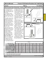
The condensate drain must be
installed and the P-trap must be
filled before starting the unit.
Location
The condensate drain is a 3/4”
FPT connection in the left bottom of
the unit, behind the compressor(s).
Select materials
Ordinary schedule 40 PVC or ABS
plastic pipe is adequate in most
cases. Do not reduce the pipe size
below that provided on the unit.
Install P-trap
If there is no condensate pump, a
drain trap must be installed. The
trap must be at least two (2) inches
deep to maintain a water seal. For
long runs or possible unintentional
traps, a vacuum breaker on the out-
let side of the P-trap may be neces-
sary. Follow standard procedures.
Route drain pipe
Route the drain pipe so that the
only trap is the P-trap. In horizontal
runs, slope the pipe downward at
least 1/4” per foot (2 cm per meter).
Deliver the condensate to a suit-
able point. Check local codes for
allowable procedures.
Fill P-trap
To prevent air from being drawn
through the condensate drain pipe,
the P-trap must be filled with water
before starting the unit blowers.
Failure to do this will cause the
drain pan to overflow during
operation.
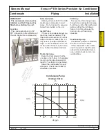
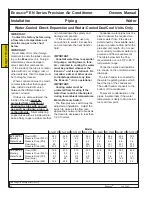
Condensate pump
Condensate pumps are standard,
with the curve shown below.
If the condensate is to be deliv-
ered to a pipe that might be pres-
surized above atmospheric pres-
sure, install a check valve to pre-
vent backflow.
25
20
15
10
5
0
1
2
3
4
5
6
7
0
0
20
40
60
80
100
100
200
300
H (ft.)
H (m)
L/h
US gph
Condensate Pump
Average Curve
Owners Manual Ecosaire
®
EN Series Precision Air Conditioner
Ecosaire
®
July 2009 23
Data subject to change without notice.
Condensate Piping Installation
INST
ALLA
TION
EXAMPLE
Appearance, location, and
quantity of component
s
may vary
.
Summary of Contents for EN Series
Page 1: ......
Page 103: ...OEM User manual ...
Page 104: ......
Page 106: ......
Page 108: ......
Page 110: ......
Page 123: ...OEM CAREL code 030221791 rel 2 1 21 09 07 15 4 2 Single phase wiring diagram INTERNAL TAM CP2 ...
Page 141: ......

