INDEX
1. MODELS AND DESCRIPTION OF THE COMPONENTS ....................................................................................................................... 3
1.1
Description of the components ............................................................................................................................................................. 3
2. INSTALLATION: dimensions, weights, hose connections........................................................................................................................... 6
2.1
Positioning............................................................................................................................................................................................ 6
2.2
Connecting the hoses............................................................................................................................................................................ 8
2.3
Drain..................................................................................................................................................................................................... 9
2.4
Supply .................................................................................................................................................................................................. 9
2.5
Checks.................................................................................................................................................................................................. 9
2.6
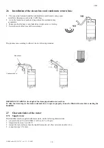
Installation of the steam hose and condensate return hose ................................................................................................................. 10
2.7
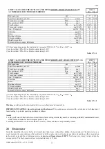
Characteristics of the water ................................................................................................................................................................ 10
2.7.1
Supply water .................................................................................................................................................................................. 10
2.8
Drain water......................................................................................................................................................................................... 11
3. OEM WITH FRAME .................................................................................................................................................................................... 12
3.1
Introduction ........................................................................................................................................................................................ 12
3.2
Frame ................................................................................................................................................................................................. 12
3.3
Control board...................................................................................................................................................................................... 12
3.4
Water fill ............................................................................................................................................................................................ 12
3.5
Drain................................................................................................................................................................................................... 13
3.6
Water circuit....................................................................................................................................................................................... 13
3.7
Structure ............................................................................................................................................................................................. 13
3.8
Switch and manual drain button ......................................................................................................................................................... 13
3.9
External connections .......................................................................................................................................................................... 13
3.10
Power cable ........................................................................................................................................................................................ 13
3.11
Current transformer (TAM)................................................................................................................................................................ 13
3.12
LED panel .......................................................................................................................................................................................... 13
3.13
Technical specifications ..................................................................................................................................................................... 13
4. ELECTRICAL CONNECTIONS (with CAREL controller, model CP)................................................................................................... 14
4.1
Single-phase wiring diagram, EXTERNAL TAM (CP1 *) ................................................................................................................ 14
4.2
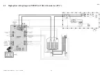
Single-phase wiring diagram, INTERNAL TAM (CP2 *) ................................................................................................................. 15
4.3
Single-phase wiring diagram, INTERNAL TAM with contactor (CP4 *) ......................................................................................... 16
4.4
Single-phase wiring diagram, EXTERNAL TAM with contactor (CP3 *) ........................................................................................ 17
4.5
Three-phase wiring diagram, EXTERNAL TAM with contactor (CP3 *) ......................................................................................... 18
4.6
Three-phase wiring diagram, INTERNAL TAM with contactor (CP4 *) .......................................................................................... 19
4.7
Three-phase wiring diagram, KUE with frame, INTERNAL TAM with contactor (CP4 *) .............................................................. 20
4.8
Single-phase wiring diagram, KUE with frame, INTERNAL TAM with contactor (CP4 *) ............................................................. 21
4.9
Three-phase wiring diagram, EXTERNAL TAM with contactor (CP3 *) ......................................................................................... 22
5. STARTING, CONTROL AND SHUTDOWN............................................................................................................................................. 23
5.1
Preliminary checks ............................................................................................................................................................................. 23
5.2
Starting ............................................................................................................................................................................................... 23
5.2.1
Starting with an empty cylinder ..................................................................................................................................................... 23
6. MAINTENANCE AND SPARE PARTS ..................................................................................................................................................... 24
6.1
Replacing the cylinder........................................................................................................................................................................ 24
6.2
Maintenance of the other components in the water circuit ................................................................................................................. 25
6.3
Component replacement..................................................................................................................................................................... 26
6.3.1
Fuses in the auxiliary circuits......................................................................................................................................................... 26
6.4
Spare parts.......................................................................................................................................................................................... 27
6.4.1
SINGLE-PHASE humidifiers: ....................................................................................................................................................... 27
6.4.2
Spare parts for special applications................................................................................................................................................ 27
6.4.3
THREE-PHASE humidifiers: ........................................................................................................................................................ 27
6.4.4
Spare parts for special applications................................................................................................................................................ 28
6.5
Troubleshooting ................................................................................................................................................................................. 29
6.6
Alarms................................................................................................................................................................................................ 29
7. OPERATING PRINCIPLE, CONTROL AND OTHER FUNCTIONS.................................................................................................... 30
7.1
Operating principle............................................................................................................................................................................. 30
7.2
Control principles............................................................................................................................................................................... 30
7.2.1
ON/OFF control - CP controllers ................................................................................................................................................... 30
7.2.2
Proportional control - CP controllers ............................................................................................................................................. 30
8. TECHNICAL SPECIFICATIONS............................................................................................................................................................... 31
Summary of Contents for EN Series
Page 1: ......
Page 103: ...OEM User manual ...
Page 104: ......
Page 106: ......
Page 108: ......
Page 110: ......
Page 123: ...OEM CAREL code 030221791 rel 2 1 21 09 07 15 4 2 Single phase wiring diagram INTERNAL TAM CP2 ...
Page 141: ......


