Firmware: V2.18 / V--
26.10.2022
22/119
1.
2.
3.
4.
The following can generally be set in the controller configuration editor:
Assignment of the physical inputs and outputs to addresses in the process image of the controller
Setting the hardware configuration, such as number of SIOX extension modules.
Setting the measuring ranges
Prioritisation of the system alarms
The assignment of the physical inputs and outputs to the IEC addresses is predefined in the controller. This
means that they are set at the factory and do not have to be configured first. The IEC addresses are needed to
connect to the symbolic names in the DDC program. This is done using the
Signal List
. Such an assignment to
a meaningful variable name is highly recommended, although names are already preset in the controller
configuration at the factory and are marked as "Default Identifier".
The above screenshot of the controller configuration shows under "Controller GLT 3010_V2" in the section
"Digital IO [FIX]" how many inputs and outputs the base module (STANDARD) and the associated
SIOX1..SIOX3 extension modules have.
In addition, for each of the last four relay outputs, there is feedback for the position of the manual control switch,
which is used to switch from Auto to Manual ON or OFF. This feedback is in the form of a digital input and can
be retrieved by the programmer.
Example:
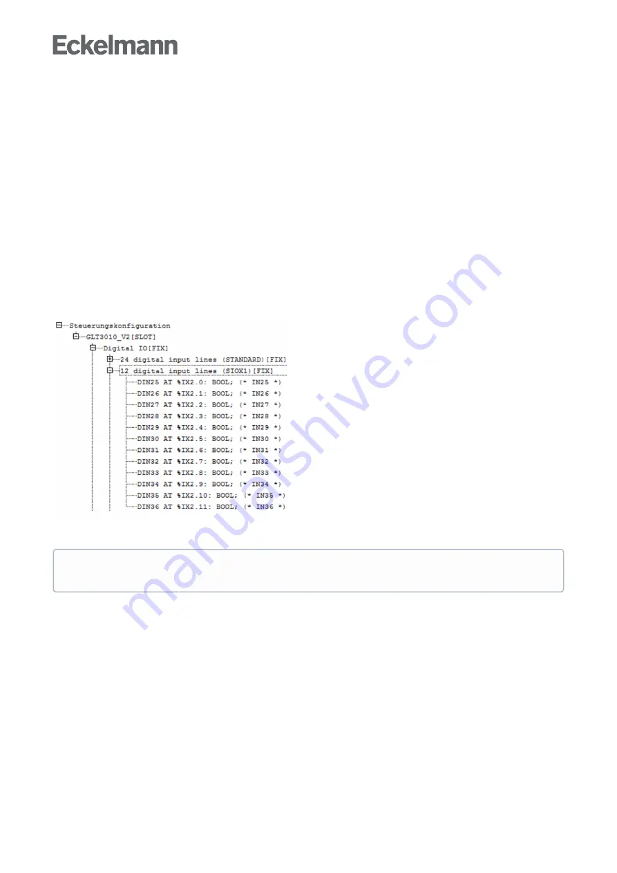
Clicking on [+] opens the following display for the SIOX 1:
Explanation:
The SIOX1 with its 12 digital inputs and the associated IEC addresses %IX2.0 .. %IX2.11.
The preset variable names DIN25 .. DIN36 can be used directly in CODESYS, e.g. for .. IF DIN34 then ...
Practical tip:
For better readability of the CODESYS program, meaningful process variable names
should be defined via the
and then used.


