


Understanding IAC Operation
4-3
EATON
Powerware
®
9390 IAC-B and IAC-T Installation and Operation Manual
S
164201590 Rev C
powerware.com
4.2 Parallel Redundant Configuration
Refer to the applicable Powerware 9390 Installation and Operation manual, listed in
paragraph 1.5, for detailed parallel theory of operation.
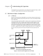
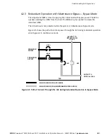
4.2.1 Redundant Operation
The IAC in redundant configuration allows two UPMs to be connected with the outputs in
parallel (tied together) to provide redundancy in a 1+1 configuration. Each UPM shares the
load equally. If one UPM should fail, the remaining UPM assumes the entire load. In a 1+1
redundant configuration the maximum load is equal to the maximum load of one UPM
only.
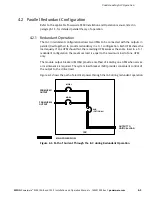
The module output breakers (MOBs) provide a method of isolating one UPM when service
or maintenance is required. The system load breaker (SLB) provides convenient control of
the output to the critical load.
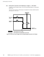
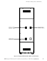
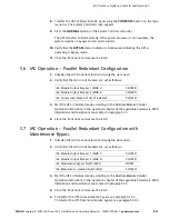
Figure 4-3 shows the path of electrical power through the IAC during redundant operation.
OUTPUT TO
CRITICAL LOAD
IAC
MOB 1
MOB 2
SLB
(OPTIONAL)
FROM UPM 1
OUTPUT
MAIN POWER FLOW
FROM UPM 2
OUTPUT
Figure 4-3. Path of Current Through the IAC during Redundant Operation
Summary of Contents for Powerware 9390 IAC-B
Page 145: ......
Page 146: ...164201590C 164201590 C...


