Installing the IAC
3-14
EATON
Powerware
®
9390 IAC-B and IAC-T Installation and Operation Manual
S
164201590 Rev C
powerware.com
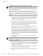
3.3.4 Installing IAC Standalone MBP Power Wiring
NOTE
The IAC is shipped with a debris shield covering the ventilation grill on top of
the unit. Do not remove the debris shield until installation is complete. However, remove
the shield before operating the IAC. Once the debris shield is removed, do not place
objects on the ventilation grill.
NOTE
Remove the IAC cabinet top or bottom conduit landing plate to drill or punch
conduit holes, or remove knockouts (see Drawing 164201590-5 on page A-32).
NOTE
Refer to the applicable Powerware 9390 Installation and Operation manual,
listed in paragraph 1.5, for UPS cabinet wiring information, and conduit and terminal
locations.
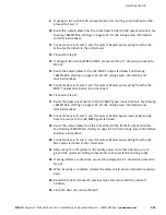
1.
Verify the UPS system is turned off and all power sources are removed. Refer to
the applicable Powerware 9390 Installation and Operation manual, listed in
paragraph 1.5, for shutdown instructions.
2.
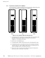
If not already open, unfasten the IAC front door latch and swing the door open.
3.
If not already removed, remove the door. Remove the retaining screws located
inside the door at the top and bottom hinge pivot points, then lift the door off.
Save the retaining screws for reinstallation of the door.
4.
If not already removed, remove the screws securing the internal safety shield
panels and remove the panels to gain access to the terminals.
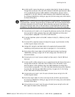
5.
Route the UPS output cables from the UPS to the IAC MIS input terminals. Refer to
the applicable Powerware 9390 Installation and Operation manual, listed in
paragraph 1.5, for UPS cabinet terminal locations and termination requirements.
See Drawing 164201590-6, starting on page A-34, for IAC wiring access information
and terminal locations.
6.
Connect phase A, B, and C, and, if required, Neutral power wiring to the UPS
output and IAC MIS input terminals.
NOTE
If a BIB is not installed, a minimum of two separate feeds with upstream feeder
breakers must be provided: one for the UPS and one for the IAC bypass input. Do not
use one feed for both UPS and IAC.
7.
Route the bypass input cables from the utility source to the IAC MBP bypass input
terminals. See Drawing 164201590-6, starting on page A-34, for IAC wiring access
information and terminal locations.
8.
Connect phase A, B, and C, and, if required, Neutral bypass input power wiring
from the utility source to the IAC MBP bypass input terminals.
9.
If wiring an IAC with a BIB, or BIB and RIB, proceed to Step 10; otherwise, proceed
to Step 19.
Summary of Contents for Powerware 9390 IAC-B
Page 145: ......
Page 146: ...164201590C 164201590 C...

