
Eaton 93E UPS 15-80 kVA (380/400/415 V)
Installation and Operation Manual
© Eaton Corporation plc 2015. All rights reserved.
Revision: 001
Document ID: 614-01975-00
80 (133)
contactors prevent system voltages from bleeding backwards through
the static switch and rectifier snubber components to the utility source.
If the input power fails to return or is not within the acceptance window
required for normal operation, the battery continues discharging until a
DC voltage level is reached where the inverter output can no longer
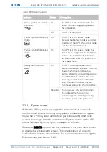
support the connected loads. When this event occurs, the UPS issues
another set of audible and visual alarms indicating
SHUTDOWN
IMMINENT
. If the bypass source is available, the UPS transfers to bypass
instead of shutting down.
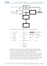
If at any time during the battery discharge the input power becomes
available again, the input and the backfeed protection contactors close
and the rectifier begins to supply DC current to the converter and
inverter. At this point, the unit returns to the normal mode. Depending
on the total load and the duration of the battery discharge, battery
current limit alarms may be seen for a short time due to the current
required to recharge the battery.
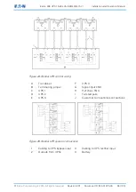
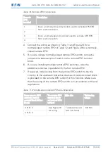
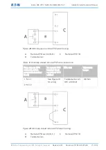
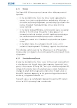
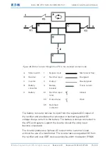
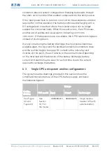
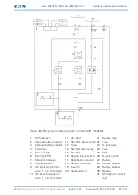
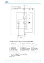
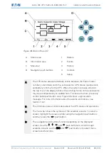
6.3
Single UPS unit system oneline configurations
The system oneline drawings provided in this section show the
simplified internal structure of the UPS, battery supply, and basic
maintenance bypass.
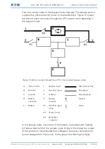
Voltage
Oneline
drawing
UPS model Input
Output
System type
See Figure
33 and
Figure 34
See
Section
10.1 for
the model
380/400/415 380/400/415 Single reverse
transfer UPS with
external battery