Eaton 93E UPS 15-80 kVA (380/400/415 V)
Installation and Operation Manual
© Eaton Corporation plc 2015. All rights reserved.
Revision: 001
Document ID: 614-01975-00
59 (133)
4.
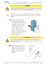
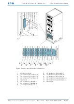
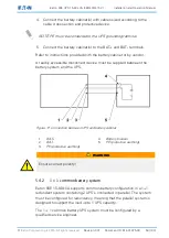
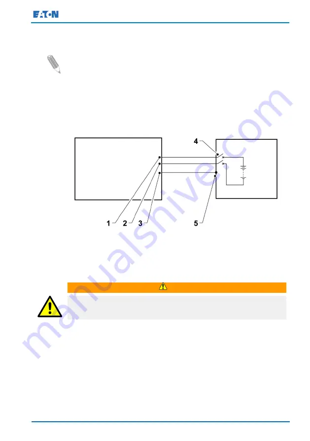
Connect the battery cabinet(s) with cables sized according to the
cable cross section and protective device.
NOTE: PE must be connected to the UPS grounding terminal.
5.
Connect the battery cabinet(s) to the BAT+ and BAT- terminals.
Refer to instructions provided with the battery cabinet or by vendor.
A readily accessible disconnect device must be supplied between the
battery system and the UPS.
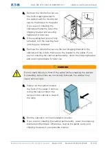
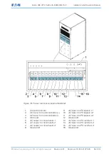
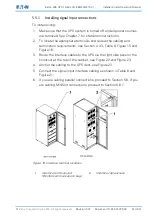
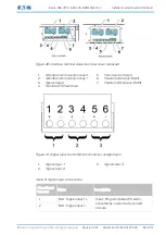
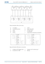
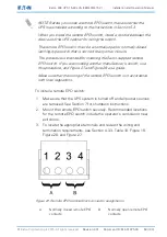
Figure 17. Connection between UPS and battery cabinet
1.
BAT+
2.
BAT–
3.
PE (protective earthing)
4.
Battery breaker
5.
PE (protective earthing)
WARNING
Ensure correct polarity!
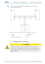
5.4.2
1 + 1 common battery system
Eaton 93E 15-80 kVA supports common battery configuration in a 1+1
redundant system containing 2 UPS's connected in parallel. The system
must be configured for redundancy, meaning that the parallel system is
designed to support the load up to 1 UPS capacity.
The 1 + 1 common battery UPS system must be configured by a
qualified service engineer.