
Eaton 93E UPS 15-80 kVA (380/400/415 V)
Installation and Operation Manual
© Eaton Corporation plc 2015. All rights reserved.
Revision: 001
Document ID: 614-01975-00
78 (133)
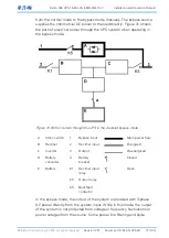
protection is provided to the load but no active power conditioning or
battery support is available to the output of the system in the bypass
mode of operation.
The internal bypass is comprised of a solid-state, silicon-controlled
rectifier (SCR) continuous duty static switch, and a backfeed protection
contactor. The static switch is used instantaneously anytime the inverter
is unable to support the applied load. The continuous duty static switch
is wired in series with the backfeed protection contactor, and together
they are wired in parallel with the rectifier and inverter.
The static switch, being an electronically-controlled device, can be
turned on immediately to pick up the load from the inverter while
inverter output relay opens to isolate the inverter. The backfeed
protection contactor (if fitted) is normally closed, ready to support the
static switch unless the bypass input source becomes unavailable.
If the UPS transfers from the normal mode to the bypass mode due to
any reason other than operator intervention, the UPS automatically
attempts to transfer back to the normal mode (up to 3 times within a 10
minute period). The 4
th
transfer locks the critical load to the bypass
source and requires operator intervention to transfer.
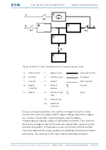
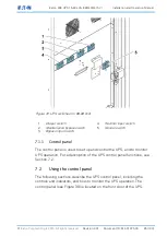
6.2.5
Battery mode
The UPS automatically transfers to the battery mode if a utility power
outage occurs, or if the utility power does not conform to the specified
parameters. In the battery mode, the battery provides emergency DC
power which the inverter converts to AC power.
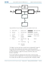
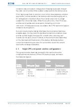
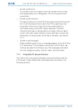
Figure 32 shows the path of electrical power through the UPS system
when operating in the battery mode.