
Eaton 93E UPS 15-80 kVA (380/400/415 V)
Installation and Operation Manual
© Eaton Corporation plc 2015. All rights reserved.
Revision: 001
Document ID: 614-01975-00
60 (133)
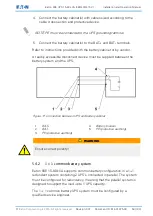
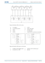
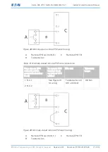
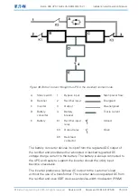
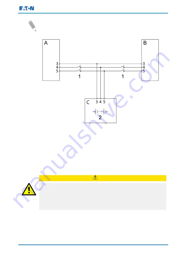
NOTE: The common battery configuration can only be used in a
system described above.
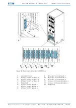
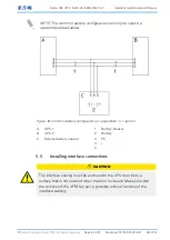
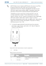
Figure 18. Common battery configuration in a redundant 1+1 system
A
UPS 1
1
Battery breaker
B
UPS 2
2
Battery
C
External battery cabinet
3
PE
4
+
5
-
5.5
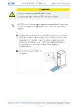
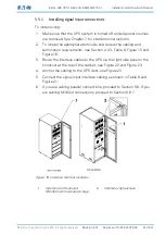
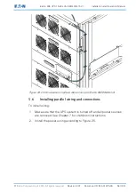
Installing interface connections
CAUTION
The interface cabling must be anchored to the UPS door (onto a
surface that is not covered when the door is closed). Make sure that
the removal of the UPM fan pan is possible without removal of the
interface cabling.