


Eaton 93E UPS 15-80 kVA (380/400/415 V)
Installation and Operation Manual
© Eaton Corporation plc 2015. All rights reserved.
Revision: 001
Document ID: 614-01975-00
25 (133)
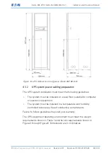
4.1
Creating an installation plan
Before you install the UPS system, read and understand how these
instructions apply to the system that you are going to install. Use the
procedures and illustrations in Section 4.3 and Chapter 5 to create a
logical plan for installing the system.
4.2
Installation checklist
Action
Yes/No
All packing materials and restraints are removed from each cabinet.
The UPS cabinet is placed in its installed location.
All conduits and cables are properly routed to the UPS and any
ancillary cabinets.
A readily accessible disconnect device is installed between the UPS
input and utility power.
All power cables are properly sized and terminated.
Neutral conductors are installed.
A ground conductor is properly installed.
(OPTIONAL) Signal inputs are wired appropriately.
(OPTIONAL) LAN drops are installed.
(OPTIONAL) LAN connections have been completed.
(OPTIONAL) The remote EPO device is mounted in its installed
location and its cabling is terminated inside the UPS cabinet.
(OPTIONAL) If a normally-closed remote EPO switch is used, a jumper
wire is connected between pins 3 and 4 on the remote EPO terminal
block.
All terminal cover plates are installed.
(OPTIONAL) Accessories are mounted in their installed locations and
their cabling is terminated inside the UPS cabinet.
Air conditioning equipment is installed and operating correctly.