
Eaton 93E UPS 15-80 kVA (380/400/415 V)
Installation and Operation Manual
© Eaton Corporation plc 2015. All rights reserved.
Revision: 001
Document ID: 614-01975-00
75 (133)
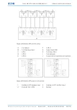
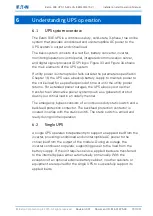
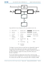
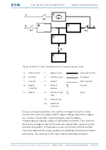
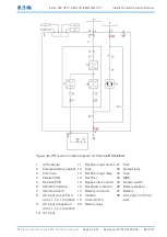
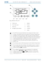
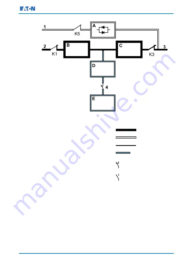
Figure 30.Path of current through the UPS in the standard normal mode
A
Static switch
1
Bypass input
Main power flow
B
Rectifier
2
Rectifier input
Energized
C
Inverter
3
Output
De-energized
D
Battery
converter
4
Battery
breaker
Trickle current
E
Battery
K1
Rectifier input
relay
Closed
K3
Output relay
Open
K5
Backfeed
contactor
The battery converter derives its input from the regulated DC output of
the rectifier and provides either a boosted or bucked regulated DC
voltage charge current to the battery. The battery is always connected to
the UPS and ready to support the inverter should the utility input
become unavailable.
The inverter produces a 3-phase AC output to the customer's load
without the use of a transformer. The inverter derives regulated DC from
the rectifier and uses IGBT devices and pulse-width modulation (PWM)