

Eaton 93E UPS 15-80 kVA (380/400/415 V)
Installation and Operation Manual
© Eaton Corporation plc 2015. All rights reserved.
Revision: 001
Document ID: 614-01975-00
70 (133)
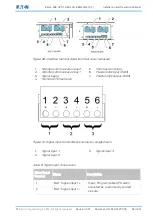
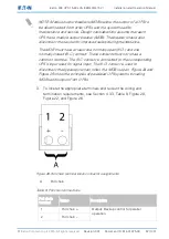
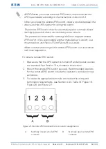
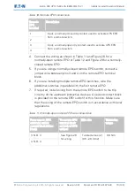
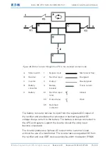
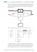
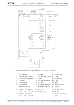
Table 10. Remote EPO connections
Remote
EPO
terminal
Description
1
Input: a normally-closed dry contact used to activate UPS EPO
from a remote switch.
2
3
Input: a normally-open dry contact used to activate UPS EPO
from a remote switch.
4
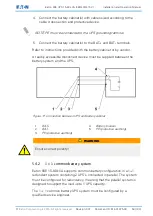
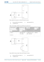
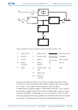
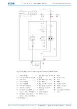
4.
Connect the wiring as shown in Table 11 and Figure 28 for a
normally-open remote EPO or Table 12 and Figure 29 for a normally-
closed remote EPO.
5.
If you are using a normally-closed remote EPO switch, connect a
jumper wire between pins 3 and 4 on the remote EPO terminal
block.
6.
If you are installing multiple remote EPO switches, wire the
additional switches in parallel with the first remote EPO.
7.
If required, install wiring from the remote EPO switch to the trip
circuitry of the upstream protective devices. A second contact block
is provided on the remote EPO switch for this function. Make sure
that the wiring of the remote EPO switch is in accordance with local
regulations.
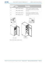
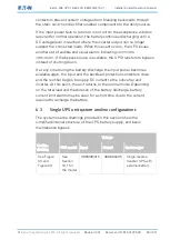
Table 11. Normally-open remote EPO wire connections
From remote EPO
station(s) switch
contact block (either
block)
To remote EPO
terminal block
on back of UPS
cabinet
Wire size
Tightening
torque
3 N.O. 3
See Figure 28
for wiring
Twisted wires (2)
(0.5 -2.0 mm2)
0.8 Nm
4 N.O. 4