
Eaton 93E UPS 15-80 kVA (380/400/415 V)
Installation and Operation Manual
© Eaton Corporation plc 2015. All rights reserved.
Revision: 001
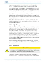
Document ID: 614-01975-00
82 (133)
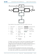
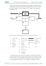
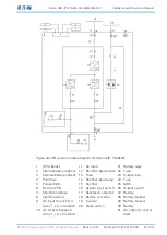
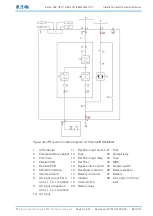
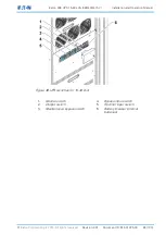
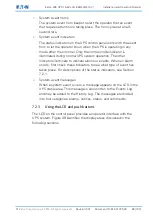
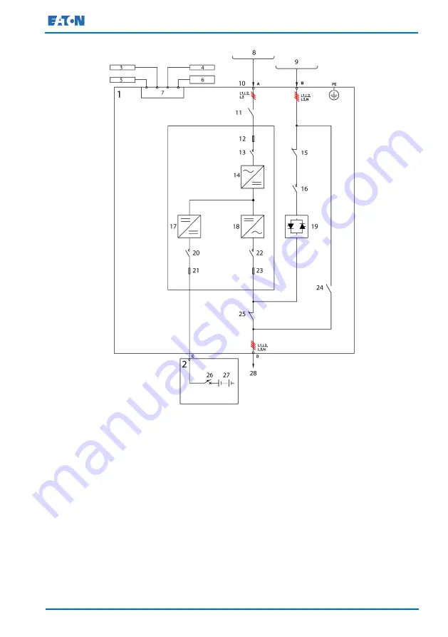
Figure 34.UPS system oneline diagram for Eaton 93E 60-80kVA
1
UPS cabinet
11 Rectifier input switch 21 Fuse
2
External battery cabinet 12 Fuse
22 Output relay
3
Pull chain
13 Rectifier input relay 23 Fuse
4
Parallel CAN
14 Rectifier
24 MBS
5
Remote EPO
15 Bypass input switch 25 Output switch
6
MiniSlot interface
16 Backfeed contactor 26 Battery breaker
7
Interface board
17 Battery converter
27 Battery
8
AC input to rectifier 3
wire L1, L2, L3 rotation
18 Inverter
28 AC output to critical
load
19 Static switch
9
AC input to bypass 4
wire L1, L2, L3 rotation
20 Battery relay
10 AC input