background image

Basic Setup Options

5B6729 – May 1997

39

Selecting the Display Language

Description:

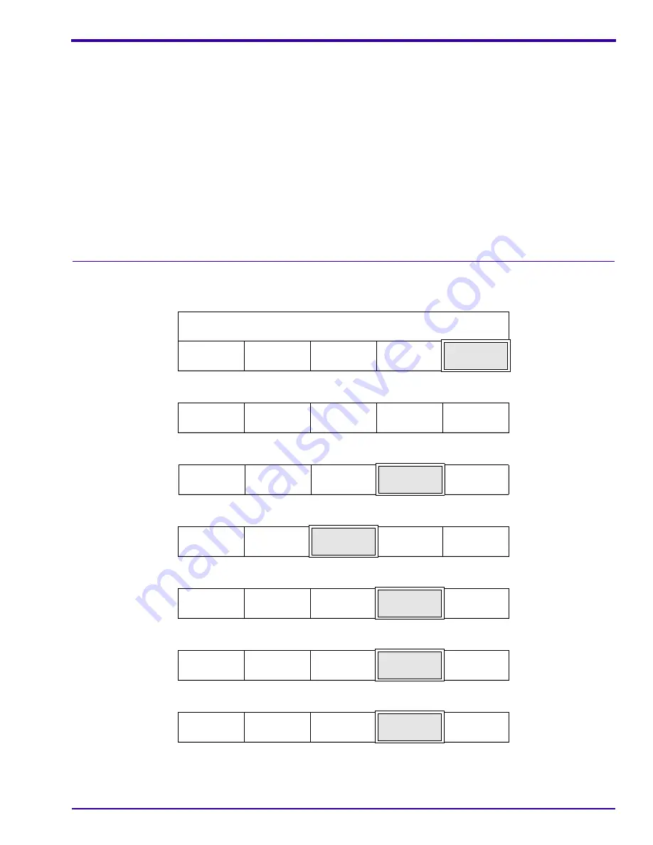
The Processor displays messages in 12 different languages:

Default Setting:  English

Procedure:

[1] From the Walk-Up Menu, press the “GO TO SETUP” key.

[2] Enter the 4-digit access code.

[3] Press the “MORE” key.

[4] Press the “OPTIONS” key.

[5] Press the “MORE” key.

[6] Press the “MORE” key.

[7] Press the “MORE” key.

Danish

Italian

Dutch

Japanese

English

Norwegian

Finnish

Portuguese

French

Spanish

German

Swedish

READY

STD

DRYER

TEMP

SLEEP

SELECT

CYCLE

MORE

GO TO

SETUP

1

2

3

4

CANCEL

REQUEST

CHEM/

CYCLE

MORE

DONE/

RETURN

INFO

SETUP

OPTIONS

DONE/

RETURN

REPLEN

MODE

DAILY

STARTUP

DISPLAY

UNITS

MORE

DONE/

RETURN

ACCESS

CODE

USER

ACCESS

TEMP

LOCK

MORE

DONE/

RETURN

STANDBY

MODE

ROLLER

JOG

COOL

DOWN

MORE

DONE/

RETURN

Summary of Contents for Kodak X-Omat 5000 RA

Page 1: ...Eastman Kodak Company Publication No 5B6729 May 1997 Supersedes January 1996 OPERATOR MANUAL for the Kodak X Omat 5000 RA Processor H148_0004AA...

Page 2: ...s no responsibility or liability whatsoever for the serviceability of any drain connected to or associated with a Kodak X Omat Processor Such drains are the sole responsibility of the customer Descrip...

Page 3: ...ng Different On and Off Times for the Remaining Days 52 Changing the On and Off Timer Settings 54 Selecting the Start Up Option 56 Entering and Exiting Sleep Mode 57 Procedure for Entering Sleep Mode...

Page 4: ...understand the instructions and procedures outlined in this manual The experienced user may only need to refer to this manual when using some of the features and functions new to the 5000 RA Processo...

Page 5: ...essor also provides 4 operator selectable film processing cycles which run at 4 default transport speeds The 4 cycles are K RA Rapid Standard Extended Each cycle has default parameters or setpoints fo...

Page 6: ...cle and Interface Control Panel H148_0061BA H148_0061BCA Panel Access Middle Access Panel Transformer Side Panel Non Drive Bin Receiving Panel Display Top Cover Tray Feed Dryer Access Panel Electrical...

Page 7: ...he following information If the Green Ready Indicator is illuminated the Processor is ready to accept film If the Yellow Wait Indicator is illuminated the Processor has not yet reached optimum film pr...

Page 8: ...w key Adjusting the Contrast of the Display Panel 1 To lighten the display press and hold Soft Key 4 on the Display Panel At the same time press Soft Key 2 on the Display Panel to obtain the desired c...

Page 9: ...re to display the current fixer temperature to place the Processor in Sleep mode to display the time and date The access code can be changed at any time by the user To change the access code follow th...

Page 10: ...g whether the new access code has been accepted 9 Press the DONE RETURN key repeatedly until you return to the display shown below Then press the YES key to return to the Walk Up Menu Note If you forg...

Page 11: ...ser Access 1 From the Walk Up Menu press the GO TO SETUP key 2 Enter the 4 digit access code 3 Press the MORE key 4 Press the OPTIONS key 5 Press the MORE key 6 Press the USER ACCESS key 7 Press the L...

Page 12: ...solution evaporated while the Processor was off the developer and fixer Tanks will be automatically replenished to their overflow levels when you turn on the Processor When film is fed the Drive Motor...

Page 13: ...and Crossovers are in their correct positions 2 Check that the Crossover Fill Trough is in position 3 Check that the 2 Water Troughs not shown are installed correctly on the bottom of the Developer F...

Page 14: ...cuit Breaker CB1 to the ON position 10 For optimum processing quality allow approximately 20 minutes for the processing solutions to reach the correct operating temperature before you feed film The Re...

Page 15: ...back films after you feed them into the Processor Do not pull on film as it exits the Processor Do not allow more than 100 sheets of films to accumulate in the Receiving Bin at one time Figure 6 X Ray...

Page 16: ...cceptable because their bases are soluble in the processing solutions Note Tape the leading edge of the roll film emulsion side up within 5 1 cm 2 in of the vertical lengthwise center of the Leader Se...

Page 17: ...the Processor If you wish you may change the setup information by using the Soft Keys on the Display Panel See the following pages for instructions on how to set up the Processor Table 1 Default Proc...

Page 18: ...inimum 35 0 C 95 F 35 0 C 95 F 35 0 C 95 F 35 0 C 95 F Developer Replenishment Volume 35 x 43 cm sheet Automatic Flooded 60 mL 65 mL 60 mL 65 mL 60 mL 65 mL 60 mL 65 mL Fixer Replenishment Volume 35 x...

Page 19: ...e refers to the film processing cycle that is currently selected Process Time refers to the time it takes the leading edge of a 35 x 43 cm 14 x 17 in sheet of film to travel from the Detector Rollers...

Page 20: ...lk Up Menu Procedure for Selecting the K RA Cycle 1 From the Walk Up Menu press the GO TO SETUP key 2 Enter the 4 digit access code 3 Press the CHEM CYCLE key 4 Press the appropriate key for the desir...

Page 21: ...ed cycle b If you selected RA chemicals press the K RA CYCLE key 6 Press the DONE RETURN key repeatedly until you return to the display shown below Then press the YES key to return to the Walk Up Menu...

Page 22: ...ibly when you change the type size or quantity of film you are processing You may choose to have the Dryer temperature setpoint displayed in either degrees Celsius C or degrees Fahrenheit F To select...

Page 23: ...formats Time Formats 12 Hour 24 Hour Date Formats where M Month D Day and Y Year M D Y D M Y Y M D Procedure 1 From the Walk Up Menu press the GO TO SETUP key 2 Enter the 4 digit access code 3 Press...

Page 24: ...e set date option 15 Press the SET DATE key 16 Press the SET DATE key 17 Use the up and down arrow keys to set the date 18 Press the DONE RETURN key once to return to the set year option 12 HOUR TIME...

Page 25: ...to display the current time and date simply press the TIME DATE key on the Display Panel The current time and date will then appear on the Display Panel Procedure 1 From the Walk Up Menu press the MO...

Page 26: ...replenishment delivered equals the replenishment volume selected Important The volume of replenishment solution actually measured during this procedure is not the volume delivered for a 35 x 43 cm sh...

Page 27: ...through 11 at least 2 more times 15 Determine the average volume of replenishment delivered 16 Install the Replenishment Hose into the respective quick disconnect Valve 17 Press the UPDATE CAL VOL ke...

Page 28: ...17 in has been processed Tank Fill Mode Select this mode to fill empty Processor Tanks automatically A warning error stating that the Tanks Currently Being Filled occurs as the Tanks are filling Afte...

Page 29: ...plenishment Tank Fill Disable Replenishment 7 Press the DONE RETURN key repeatedly until you return to the display shown below Then press the YES key to return to the Walk Up Menu REPLEN MODE DAILY ST...

Page 30: ...and Heater turn on as needed to maintain the temperature of the Dryer the wash water turns on every 8 minutes and remains on for 90 seconds to clean the Rollers the solution Heaters remain on as need...

Page 31: ...y for the Interval Mode the CONT key for Continuous Mode 9 Press the DONE RETURN key repeatedly until you return to the display shown below Then press the YES key to return to the Walk Up Menu STANDBY...

Page 32: ...sound until you press the DONE RETURN key or until the screen time out expires Default Setting Mid Range 7 Accepted Range 0 15 Procedure 1 From the Walk Up Menu press the GO TO SETUP key 2 Enter the...

Page 33: ...press the appropriate key key to increase the volume key to decrease the volume 10 Press the DONE RETURN key repeatedly until you return to the display shown below Then press the YES key to return to...

Page 34: ...he specified temperature range Default Setting Off Important When using accessory equipment the Temperature Lockout must be OFF to prevent the accessory equipment from attempting to feed films with th...

Page 35: ...sic Setup Options 5B6729 May 1997 35 8 Press the DONE RETURN key repeatedly until you return to the display shown below Then press the YES key to return to the Walk Up Menu EXIT SETUP YES CANCEL REQUE...

Page 36: ...cess code 3 Press the MORE key 4 Press the OPTIONS key 5 Press the DISPLAY UNITS key 6 Press either key ENGLISH for F and in min or METRIC for C and cm min 7 Press the DONE RETURN key repeatedly until...

Page 37: ...s always on Default Setting Safelight Mode Procedure 1 From the Walk Up Menu press the GO TO SETUP key 2 Enter the 4 digit access code 3 Press the MORE key 4 Press the OPTIONS key 5 Press the MORE key...

Page 38: ...e Safelight mode or ACCY key for the Accessory mode 10 Press the DONE RETURN key repeatedly until you return to the display shown below Then press the YES key to return to the Walk Up Menu RECEPTACLE...

Page 39: ...Press the OPTIONS key 5 Press the MORE key 6 Press the MORE key 7 Press the MORE key Danish Italian Dutch Japanese English Norwegian Finnish Portuguese French Spanish German Swedish READY STD DRYER TE...

Page 40: ...atedly until you return to the display shown below Then press the YES key to return to the Walk Up Menu RECPT MODE ALARM VOLUME MORE DONE RETURN LANG MORE DONE RETURN LANGUAGE IS ENGLISH ENGLISH FRENC...

Page 41: ...t Developer Setting Varies with Cycle Selected Default Fixer Setting Varies with Cycle Selected Procedure 1 From the Walk Up Menu press the GO TO SETUP key 2 Enter the 4 digit access code 3 Press the...

Page 42: ...he default setpoint temperature CANCEL REQUEST to cancel the procedure 11 Do Steps 9 and 10 for the fixer or the developer solution 12 Press the DONE RETURN key repeatedly until you return to the disp...

Page 43: ...eading will then be displayed for the fixer solution Note The setpoint temperature for the fixer solution is a minimum only the temperature may rise above this setpoint Procedure 1 From the Walk Up Me...

Page 44: ...hment volumes from the factory default settings follow the procedure outlined below Procedure 1 From the Walk Up Menu press the GO TO SETUP key 2 Enter the 4 digit access code 3 Press the MORE key 4 P...

Page 45: ...to the default volume CANCEL REQUEST to cancel the procedure 11 Press the DONE RETURN key repeatedly until you return to the display shown below Then press the YES key to return to the Walk Up Menu PR...

Page 46: ...ration Switch locatednext to the Replenishment Hoses See the figure 5 Allow the Replenishment Pumps to turn on and deliver the preset volume of replenishment solution 6 Compare the volume of replenish...

Page 47: ...below Procedure 1 From the Walk Up Menu press the GO TO SETUP key 2 Enter the 4 digit access code 3 Press the MORE key 4 Press the SETUP key 5 Press the PROCESS key 6 Press the appropriate key for the...

Page 48: ...AULT SETTING to return to the default speed CANCEL REQUEST to cancel the procedure 10 Press the DONE RETURN key repeatedly until you return to the display shown below Then press the YES key to return...

Page 49: ...portant When you are setting the Timers if the current time is later than the programmed off time the Processor will not automatically turn itself off until that time the following day You will have t...

Page 50: ...rocedure 7 Press the ON key 8 Press the SET TIMERS key Setting the On Time 9 Press the TIMER1 CONTROL key 10 Press the ON key CHEM CYCLE MORE DONE RETURN INFO SETUP OPTIONS DONE RETURN PROCESS CLOCK A...

Page 51: ...imer2 14 Press the OFF TIME key 15 Use the up and down arrow keys to select the hour and minute when you want the Processor to turn off 16 Press the DONE RETURN key repeatedly until you return to the...

Page 52: ...the display to show Tuesday 2 Press the COPY PREV key You will hear a beep when you press the COPY PREV key 3 Repeat the entire process to set the Automatic Timers for the remaining days of the week S...

Page 53: ...urn to the menu options displayed below Press the TIMER2 CONTROL key 12 Repeat Steps 7 through 11 to set the on and off time settings for Timer2 13 Repeat the entire process to set the Automatic Timer...

Page 54: ...TUP key 6 Press the SET TIMERS key 7 Press either the TIMER1 CONTROL or TIMER2 CONTROL key 8 Press either the ON TIME or the OFF TIME key READY STD DRYER TEMP SLEEP SELECT CYCLE MORE GO TO SETUP 1 2 3...

Page 55: ...time the screen shown above appears on the Display Panel you can press the OFF key to erase the last programmed on and off times for Timer1 and Timer2 11 When you are through changing the on and off...

Page 56: ...git access code 3 Press the MORE key 4 Press the OPTIONS key 5 Press the DAILY STARTUP key 6 Press the appropriate keys to select the day for which you wish to turn on or turn off the Automatic Start...

Page 57: ...up screens You can manually place the Processor in or out of Sleep mode in either of 2 ways Simply use the Key located on the feed end of the Processor Or use the Soft Keys on the Display Panel to pla...

Page 58: ...ROCESSOR IN SLEEP MODE If you have entered Sleep mode by pressing the Switch on the feed end of the Processor and you have not programmed the Automatic Timers the Processor will also display the messa...

Page 59: ...or until the fixer temperature goes below 27 C 80 F The transport and Recirculation Pump turn on for 90 seconds every 10 minutes during the cool down period The wash water turns on when the transport...

Page 60: ...the Roller Jog option the OFF key to disable the Roller Jog option 9 Press the DONE RETURN key repeatedly until you return to the display shown below Then press the YES key to return to the Walk Up Me...

Page 61: ...ion the OFF key to disable the Cool Down option 9 Press the DONE RETURN key repeatedly until you return to the display shown below Then press the YES key to return to the Walk Up Menu READY STD DRYER...

Page 62: ...ess the INFO key 5 Press the USAGE key 6 Press the DEV USAGE key The current volume of developer used and the date that the accumulation began will appear on the Display Screen 7 Press the DONE RETURN...

Page 63: ...E RATE key The average volume of developer replenishment used per single sheet of film processed will appear on the Display Screen To clear the developer rate information do the steps below 8 Press th...

Page 64: ...veloper usage information and reset it to zero the CANCEL REQUEST to continue recording the developer usage volume without resetting the volume to zero 10 Press the DONE RETURN key repeatedly until yo...

Page 65: ...ss the USAGE key 6 Press the FIXER USAGE key The current volume of fixer used and the date that the accumulation began will appear on the Display Screen 7 Press the DONE RETURN key repeatedly until yo...

Page 66: ...y 5 Press the USAGE key 6 Press the FIXER USAGE key 7 Press the USAGE RATE key To clear the fixer rate information do the steps below 8 Press the CLEAR USAGE key to clear both the total volume usage a...

Page 67: ...sage information and reset it to zero the CANCEL REQUEST to continue recording the developer usage volume without resetting the volume to zero 10 Press the DONE RETURN key repeatedly until you return...

Page 68: ...Procedure 1 From the Walk Up Menu press the GO TO SETUP key 2 Enter the 4 digit access code 3 Press the MORE key 4 Press the INFO key 5 Press the USAGE key 6 Press the SETUP GROUPS key 7 Press the app...

Page 69: ...Page 68 that allows you to determine which film size you wish to include in each setup group Procedure 1 From the Walk Up Menu press the GO TO SETUP key 2 Enter the 4 digit access code 3 Press the MO...

Page 70: ...teps below 8 Press the CLEAR USAGE key 9 When prompted ARE YOU SURE press the appropriate key the YES key to clear the film usage information and reset it to zero for all film sizes the CANCEL REQUEST...

Page 71: ...appear on the Display Screen the BOOT key to display the boot version the MAIN key to display the main program version the ACCUM BOOT key to display the accumulator boot version the ACCUM MAIN key to...

Page 72: ...hould never have any need to access these options These options should be accessed only by a trained service provider The DIAG key allows a trained service provider access to the internal diagnostics...

Page 73: ...processing cycle that you selected See the table on Page 19 3 Following all directions provided with the solutions mix at least 19 litres 5 gallons of each solution Filling the Processor Tanks Figure...

Page 74: ...normal Processor warm up period begins 10 Press the TANK FILL key 11 Press the DONE RETURN key repeatedly until you return to the Walk Up Menu 12 If you are using RP chemicals wait until the Tanks hav...

Page 75: ...nd Developer Drain Valves Note The Wash Tank does not need to be drained The Wash Tank drains automatically when you de energize the Processor Figure 12 Opening or Closing the Fixer and Developer Drai...

Page 76: ...OPERATORS MANUAL 76 May 1997 5B6729...

Page 77: ...ETURN 12345 GAL 10 21 96 CLEAR USAGE USAGE RATE DONE RETURN 85 ML DEV USAGE SHEET DONE RETURN 34567 L 05 13 96 CLEAR USAGE USAGE RATE DONE RETURN 254 ML FIXER USAGE SHEET DONE RETURN 99999 6 5 X 8 5 I...

Page 78: ...ON TO SELECT DONE RETURN SET DATE SET YEAR YEAR YEAR DONE RETURN 1996 CURRENT YEAR 10 31 CURRENT DATE MONTH MONTH DAY DAY DONE RETURN M D Y DATE DISPLAY FORMAT M D Y FORMAT D M Y FORMAT Y M D FORMAT D...

Page 79: ...TON TO SELECT STANDBY MODE ROLLER JOG COOL DOWN MORE DONE RETURN ROLLER JOG IS ON ON OFF DONE RETURN PRESS BUTTON TO SELECT RECEPT MODE ALARM VOLUME MORE DONE RETURN 10 CURRENT ALARM VOLUME DONE RETUR...

Page 80: ...OPERATORS MANUAL 80 May 1997 5B6729 This page is intentionally blank...

Page 81: ...o your service provider 1 Move the main Circuit Breaker CB1 on the Processor to the OFF position and the wall power switch to the OFF position 2 Turn off the water supply 3 Remove the Top Cover 4 Disc...

Page 82: ...n all Crossovers and on the Wash Rack rotate freely Check the squareness of the Crossovers and the Wash Rack 11 Check that the Water Troughs are not broken or cracked and that they are installed corre...

Page 83: ...ible temperature consistent with good film drying quality Clean the Feed Tray and Detector Rollers Change any chemicals that were not mixed correctly are exhausted or are contaminated Change the Devel...

Page 84: ...ugh the wall check that there are no leaks in the Lighttight Gasket If 10 x 10 cm films fail to transport reliably feed the sheets of films diagonally Check the time delay For all transport speeds the...

Page 85: ...does not cover circumstances beyond the control of Kodak misuse abuse attachments accessories alterations not marketed by Kodak including service or parts to correct problems resulting from the use of...

Page 86: ...OPERATORS MANUAL 86 May 1997 5B6729 This page is intentionally blank...

Page 87: ...6729 2649 062 47 87 88 covers om3425_1_062 doc Graphic Unification plus minor edits May 1997 5B6729 2649 142 5 7 8 10 18 23 36 43 46 49 58 77 84 om3425_1_142 doc Updated manual to reflect new software...

Page 88: ...om342500 fm Printed In USA HEALTH IMAGING EASTMAN KODAK COMPANY ROCHESTER N Y 14650 Kodak and X Omat are trademarks...

Reviews: