Settings
39
© 2019 DynaGen Technologies Inc
TOUGH Series Manual
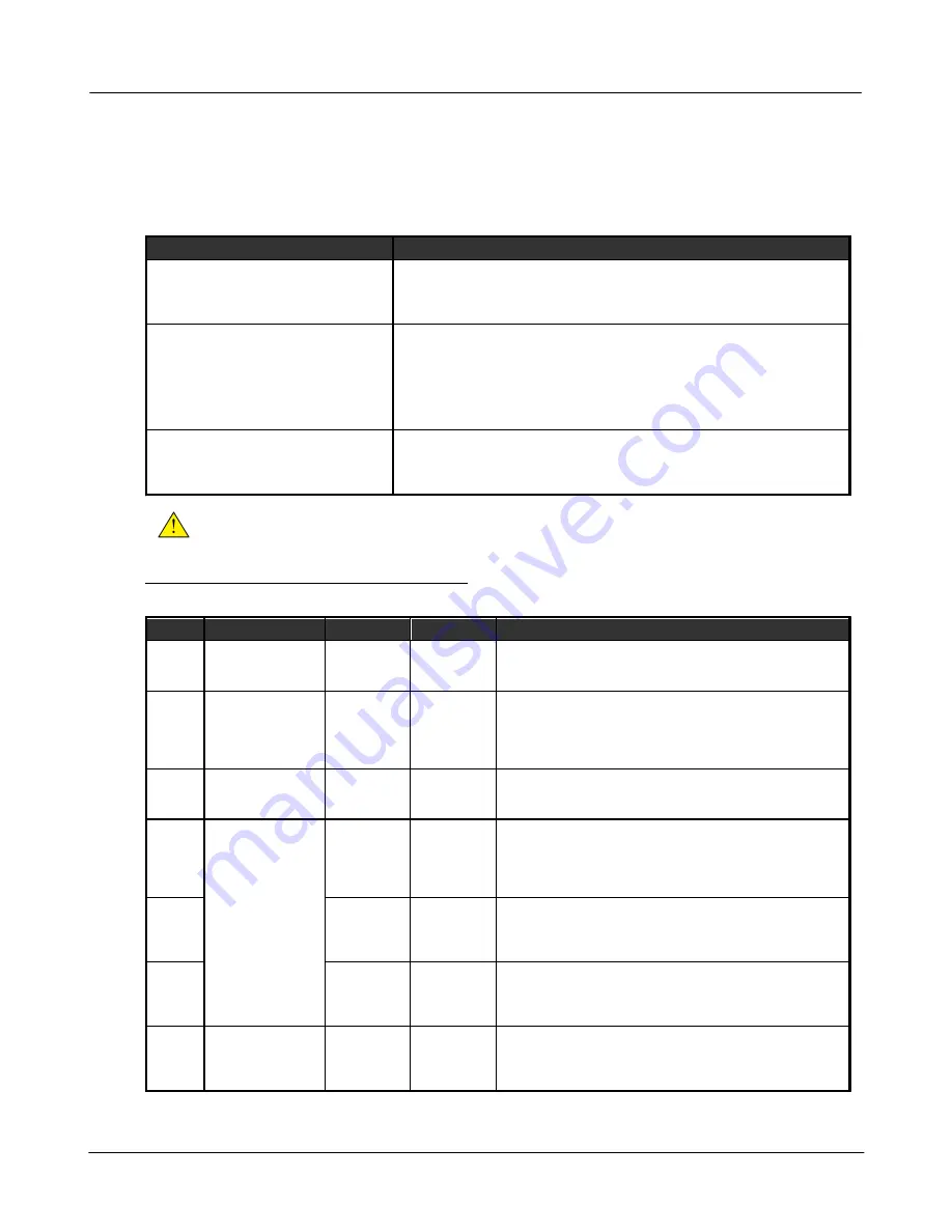
4.4.4.1 Front Panel Speed Control
The operator is able to adjust the speed of the engine by using the controller's front panel. This section describes the two
methods available for implementing speed control, the settings and parameters to be used, as well as the necessary
instructions allowing the operator to control the speed.
Speed Control Methods
Setting
Description
Front Panel Speed Control using J1939
TSC1
The controller can instruct the ECM of an electronic engine to adjust its speed by
broadcasting the TSC1 command.
Refer to the J1939 Manual for more information.
Front Panel Speed Control using Switched
Outputs
The controller can instruct the ECM of an electronic engine to adjust its speed by
using switched outputs on the controller set to RPM Increment and RPM
Decrement to interface with digital inputs on the ECM. When the speed is
changed, the corresponding switched output will be on for 1 second each time
increment or decrement is pressed.
See the rest of this section for more information.
Aux 4 Speed Control
The Auxiliary sensor 4 is used to determine the setpoint speed. The speed is
adjusted with the TSC1 J1939 command.
Refer to the J1939 Manual for more information.
WARNING
: Switched outputs have a floating voltage of approximately 8V when off. If using the outputs for digital
logic, it will be necessary to put a pull-down resistor (1kOhm, 1 Watt) from the output to ground to ensure a low
logic level when output is off.
Front panel speed control using the Switched Outputs
Settings
Name
Parent Menu
Range
Default
Description
Speed
Control
Enable
RapidCore only.
Engine Speed
menu.
Enable or
Disable
Disable
(Programmable from RapidCore Configuration Software only)
Enables or disables front panel speed control.
RPM
Display
Sensors > Engine
Speed
Blank
AC Hertz
Aux Sensor 1
Aux Sensor 2
AC Hertz
Parameter to display when adjusting speed from front panel.
This is used to provide operator feedback in the case that the
engine RPM affects another parameter such as AC
Frequency or an Auxiliary Sensor (Example: Flow rate of
pump).
Limit
Method
RapidCore only.
Engine Speed
menu.
Speed Bias
Min RPM /
Max RPM
Speed Bias
(Programmable from RapidCore Configuration Software only)
The method in which the minimum and maximum speeds the
operator is allowed to adjust is determined.
Speed
Bias
Sensors > Engine
Speed > RPM
Control
0 ~ 600 RPM
in 1 RPM
increments
30 RPM
The minimum or maximum RPM that the engine speed can be
adjusted around the Rated RPM. Example: Rated RPM is
1800 and Speed Bias is 150. The minimum RPM will be 1650
and maximum RPM will be 1950. Only valid when the correct
limit method is chosen.
Min
Speed
500 ~ 4000
RPM in 1
RPM
increments
600 RPM
The minimum RPM that can be set using speed control. Only
valid when the correct Limit Method is chosen.
Max
Speed
500 ~ 4000
RPM in 1
RPM
increments
2000 RPM
The maximum RPM that can be set using speed control. Only
valid when the correct Limit Method is chosen.
Tsc1
RPM/s
Sensors > Engine
Speed > RPM
Control
Disable, 10 ~
300 RPM/s in
10 RPM/s
increments
200 RPM
Ignore this setting. Refer to the J1939 reference manual for
information on this setting.
Speed Control Instructions
Summary of Contents for Tough Series
Page 4: ...3 2019 DynaGen Technologies Inc TOUGH Series Manual User Guide ...
Page 11: ...Installation 10 2019 DynaGen Technologies Inc TOUGH Series Manual 2 3 Wiring Harnesses ...
Page 12: ...Installation 11 2019 DynaGen Technologies Inc TOUGH Series Manual 2 4 Typical Wiring Diagram ...
Page 17: ...Installation 16 2019 DynaGen Technologies Inc TOUGH Series Manual ...
Page 19: ...Installation 18 2019 DynaGen Technologies Inc TOUGH Series Manual ...


