MAR-000276_v.1.3
Chapter:
Introduction
Page 1 of 48
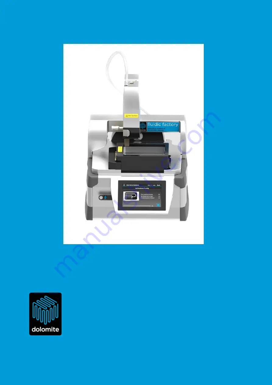
Fluidic Factory
USER MANUAL
Version: 1.0
Author: AM
Date: xx/xx/2016
P/N: xxxxxxx
Fl
P/N:
Fluidic Factory 3D Printer
Version: 1.3
Date: 16/03/2016
Part Number MAR-000276
Page 1: ...3 Chapter Introduction Page 1 of 48 Fluidic Factory USER MANUAL Version 1 0 Author AM Date xx xx 2016 P N xxxxxxx Fluidic Factory 3D Printer USER MANUAL Version 1 3 Author AM Date 16 03 2016 Part Num...
Page 2: ...ing the Fluidic Factory 24 5 1 Date and Time Settings 24 5 2 Recent Samples 24 5 3 External Storage 25 5 4 Tools 25 5 4 1 Move printer to home position 25 5 4 2 Move printer to cleaning position 26 5...
Page 3: ...MAR 000276_v 1 3 Chapter Introduction Page 3 of 48 7 Support 43 7 1 Servicing 43 7 2 Cleaning 43 7 3 FAQ 43 8 Appendices 44 8 1 Appendix A Technical Specifications 44 8 2 Appendix B Error Codes 45...
Page 4: ...gent software The desktop PC software analyses the 3D geometry of the device and identifies the internal voids and surfaces The print paths are then created from the inside of the device outwards and...
Page 5: ...d bead forms a fluidically sealed channel Features are created by adding layers with an obround cross sectional area cylinder with flattened parallel top and bottom and semi cylindrical sides As adjac...
Page 6: ...Non auto fluorescent Excellent resistance towards water soluble chemicals acids alkalis and alcohols Biocompatible Very low water absorption Compatible with various sterilizing processes Excellent mec...
Page 7: ...Robotic parts may move without warning The Fluidic Factory should only be used by competent suitably trained personnel after they have read and understood this manual and considered any hazard involv...
Page 8: ...e the warranty Cleaning Cleaning should only be performed by personnel trained in such work and who are aware of the possible dangers involved The Fluidic Factory and all the associated hardware has n...
Page 9: ...c Factory Page 9 of 48 3 Using the Fluidic Factory 3 1 Overview Print Head Heated Print Bed On off Button Induction Heater USB Socket Print Head Release and Fitting Catch Figure 2 Front View Filament...
Page 10: ...AR 000276_v 1 3 Chapter Using the Fluidic Factory Page 10 of 48 Mains Socket and Power Switch Filament Reel Holder Position Sockets for Service Personnel only Filament Tensioning Arm Figure 3 Rear Vie...
Page 11: ...Fluidic Factory Page 11 of 48 Filament Guide Filament Guide Holder Interface Plate Filament Tensioning Arm Cooling Fan Print Head Release and Fitting Catch Print Nozzle Gearbox Release Catch Inductio...
Page 12: ...ic Factory Page 12 of 48 Figure 5 below shows the interface at the Home Screen position Figure 5 Home Screen Interface Clock and Date Adjust Tools Selector External Storage Tab Recent Samples Tab Fila...
Page 13: ...ry Page 13 of 48 3 2 Box Contents When you open the box containing your Fluidic Factory ensure that you have all of the following parts as shown in Figure 6 below Component Image Core unit Part Number...
Page 14: ...ent guide x4 Part Number 3200504 Please note for your convenience the first one of these assemblies comes ready fitted into the Filament Reel Holder Filament Reel Holder Part Number 3200501 Heated Pri...
Page 15: ...d by clipping it on the interface plate The Release Engage Catch must be used to engage the Print Head see section 4 1 1 Fit the clean Print Bed Insert into the Heated Print Bed where it is magnetical...
Page 16: ...the Gearbox clockwise pushing firmly on the bottom left corner of the Gearbox to lock it into place Release the arm see section 4 1 4 Power up the Fluidic factory by pressing the Power Switch at the r...
Page 17: ...o print and start the print run see section 5 2 and 5 3 4 1 Assembly Instructions Once the Fluidic Factory is unpacked it only takes 10 minutes to assemble and start printing The following components...
Page 18: ...osition If it is not already manually pull the Interface Plate upwards until the Release Catch is above the case work as shown See Figure 7 for the correct position and Figure 8 for the incorrect posi...
Page 19: ...andle on the right facing away from the electrical contacts The Bed Insert is held in place by magnetic force See Figure 12 Slide the Bed Insert so that it is justified to the bottom right hand corner...
Page 20: ...c Factory See Figures 16 and 17 Ensure that the Filament Guide is pushed into the recess on the Filament Reel Holder See Figure 18 Figure 8 Figure 18 Figure 16 Figure 17 CAUTION The filament is slight...
Page 21: ...rm and push the Print Nozzle as far as it will go into the recess but without forcing it Release the arm See Figure 19 and 20 With the Print Nozzle correctly in situ it will look as shown See Figure 2...
Page 22: ...h up See Figure 24 Push back the Filament Tensioning Arm rotate the Gearbox clockwise pushing firmly on the bottom left corner of the Gearbox to lock it into place Release the arm See Figures 25 and 2...
Page 23: ...E Now that the Fluidic Factory is powered up it will move during many operations Ensure that the Fluidic Factory if free from any foreign objects including hands Failure to do this may result in perso...
Page 24: ...cess this menu see Figure 4 Change the Day Month and Year with the roller wheels and tap Done This will jump to the time which is changed in the same way Tap done again to return to the home screen Se...
Page 25: ...her by taping the Tools icon on the top left of the screen or sliding the left edge of the screen to the right Scroll down the screen to see all of the options See Figure 35 The following tools are av...
Page 26: ...zle and the print bed These actions are 1 Moving refitting the Print Bed or Print Bed Insert 2 Re fitting the Print Head 3 Replacing a Filament Coil Print Nozzle assembly 4 Re attaching a broken filam...
Page 27: ...ial installation ensure that the Interface Plate is above the casing of the Fluidic Factory Push in the Release and Fitting Catch and pull gently outwards at the top of the Print Head See Figure 39 Al...
Page 28: ...hen the export is complete See Figure 43 5 4 7 Device information This tab contains information including product information version numbers manufacture date and instrument status See Figure 44 5 5 S...
Page 29: ...ow to start the print run See Figure 45 During the run live information about the remaining print time bed temperature and nozzle temperature will be displayed See Figure 46 5 6 Aborting a Print Run T...
Page 30: ...pport the back of the instrument whilst push the right hand side of the Gearbox Release Catch See Figure 48 and 49 Support the Gearbox from underneath and rotate anti clockwise See Figure 50 Once it h...
Page 31: ...er along with the empty reel by lifting upwards Push in the centre button to remove the Filament Coil from the holder The empty reel should be disposed of See Figure 53 Figure 53 Figure 52 NOTICE The...
Page 32: ...e and Gearbox as described in section 4 1 3 and 4 1 4 5 8 Recovering a Broken Filament Remove the Gearbox See Section 5 7 Figures 48 to 51 Pull off the Filament Guide leaving the Print Nozzle in situ...
Page 33: ...rough the Filament Guide to allow it to be pushed through the hot Print Nozzle with forceps tweezers See Figure 58 Take the end of the Filament and push into the Print Nozzle See Figure 59 Continue to...
Page 34: ...AD software and then saved as a stl file which carries information about the surfaces of the model The Fluidic Factory PC software accepts stl files and outputs print files phff This software is suppl...
Page 35: ...1 3 Chapter Creating New Print Files Page 35 of 48 Confirm that the installation should commence See Figure 64 The installation will continue See Figure 65 And complete See Figure 66 Figure 64 Figure...
Page 36: ...the Print Bed and review the design 3 Review Print Path visualise the path the Fluidic Factory will take to print the chip 4 Export Transfer the phff file to a storage location on your PC or onto a US...
Page 37: ...pter Creating New Print Files Page 37 of 48 Select the print options as required and click Next See Figure 67 The stl file may take several minutes to convert depending on the size of the file See Fi...
Page 38: ...an be changed by clicking on and dragging the chip to the preferred position This is useful if printing multiple chips Click Back to change the stl file or click Next to move to the next section See F...
Page 39: ...eviewed Click on the next button to go to the Export File tab See Figure 70 6 2 4 Export The finalised design can now be visualised and information about the length of filament that will be required a...
Page 40: ...rors Errors can be split into 2 categories minor and major Chips with minor errors will warn that there are design errors but the run will still be printed These are shown in Amber Chips with major er...
Page 41: ...own in Figure 72 Major Errors An example of a minor error is shown in Figure 73 In this particular circumstance the size of the chip is too large for the print bed and is remedied by choosing another...
Page 42: ...MAR 000276_v 1 3 Chapter Creating New Print Files Page 42 of 48 Figure 73 NOTE For a full list of errors common error sources and fixes see Appendix C...
Page 43: ...hannels it is normal for the print head to stop moving whilst the COC hardens Q The coil has run out of COC mid run Can the printing be resumed once another loaded coil has been fitted No you will nee...
Page 44: ...items Print time 20 mins small 15 x 15 x 2 mm 1 hr medium 40 x 15 x 4 mm 24 hr large 85 x 50 x 25 mm Operating temperature range 5 to 40 C Operating humidity range Max 80 RH Length of COC coil 60 met...
Page 45: ...upport dolomite microfluidics com if this problem persists 6 Probe hit reference switch raising probe from bed Check that the bed is correctly fitted 7 Print head is powered down Restart contact suppo...
Page 46: ...microfluidics com if this problem persists 33 Extruder board has rejected the unknown command Restart contact support dolomite microfluidics com if this problem persists 34 Extruder board rejected re...
Page 47: ...s gone into error Restart contact support dolomite microfluidics com if this problem persists 108 Inductor has gone over voltage Restart contact support dolomite microfluidics com if this problem pers...
Page 48: ...MAR 000276_v 1 3 Chapter Appendices Page 48 of 48...