background image

ConÞguring the DL600E Unit

3-21

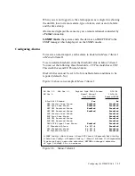
ConÞguring for SNMP

ConÞgure each unit for 

SNMP

 management functionality in

 Menu-0 SNMP 

ConÞg.

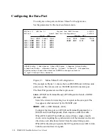
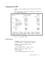
In the example in Figure 

3-5

 the remote is a 

DL600E unit, a Solo E1 DSV unit, or 

a Solo E1 Ensemble Shelf Module

.

SW Ver 1.0  MIB Ver 1.1   Digital Link DL600 Encore

4/22/95

HW Ver A

Memu-0 SNMP Config.

12:56:56

  Local:  OAHU


Remote:  MAUI

UNIT SNMP

Disabled

Disabled

IP Address

0.0.0.0

0.0.0.0

        IP Mask

0.0.0.0

0.0.0.0

        Forward Over IBC

Disabled

Disabled

TRAP

1st NMS IP Address

0.0.0.0

0.0.0.0

2nd NMS IP Address

0.0.0.0

0.0.0.0

3rd NMS IP Address

0.0.0.0

0.0.0.0

Output Port

COMM

IBC

Community Strings 

Get


public

public

Set


public

public

Trap


public

public

0-SNMP Config.  1-Main Status   2-Data DTE Status   3-Reports  4-Main Config.

5-Data Port Config.  6-Timeslot Config.  7-Alarm I   8-Alarm II  9-Diagnostics 

Type Arrow keys to move the selection, RETURN to change a selection

or type 0 through 9 for a new menu:

Figure 3-5

Menu-

0 SNMP

 ConÞg.

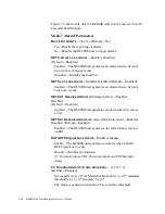
SNMP Parameters

Unit SNMP

ÑEnabled or Disabled  (DefaultÑDisabled)

Enabled

ÑEnables use of a 

SNMP

 management application.

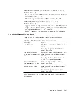
IP address

Ñnnn.nnn.nnn.nnn (DefaultÑ

0.0.0.0)

nnn = 

through

 255

Enter the 

DL600E


IP

 address.   ExampleÑ

192.84.33.6

I P  Mask

Ñnnn.nnn.nnn.nnn  (DefaultÑ

0.0.0.0)

nnn = 

through

 255

Enter the 

DL600E


IP

 mask. ExampleÑ

255.255.255.0

Summary of Contents for DL600E

Page 1: ...DL600EE1 DataMultiplexer User s Guide...

Page 2: ......

Page 3: ...mitted or reproduced in any way including but not limited to photocopy photograph magnetic chemical or other record without the prior agreement and written permission of Digital Link Corporation Digit...

Page 4: ...total liability for any and all losses and damages arising out of any cause whatsoever whether such cause is based in contract negligence strict liability other tort or otherwise shall in no event exc...

Page 5: ...bility or tness for any particular purpose Further Digital Link Corporation reserves the right to revise this publication and to make changes in it from time to time without obligation to notify any p...

Page 6: ...uctured including protection tests Under 89 336 EEC as amended by 92 31 EEC and 93 68 EEC the DL600E was tested in accordance with EN50081 1 1995 and EN50082 1 1994 to the following stan dards EN55022...

Page 7: ...2 DL600E Features 1 4 About the Telnet Utility 1 5 Applications 1 5 Chapter 2 Installing the DL600E Unit 2 1 Preparing for the Installation 2 2 Checking the Equipment 2 2 Equipment Model Numbers 2 3...

Page 8: ...ocating Timeslots 3 17 Two Allocation Methods 3 17 Configuring for SNMP 3 21 SNMP Parameters 3 21 Configuring Two Levels of Access Rights 3 23 Superuser Access Rights 3 23 Assigning User Passwords 3 2...

Page 9: ...eslot Allocation 5 15 The TIMESLOT CONFIG Menu 5 15 Allocating Timeslots Contiguously Example 5 16 Configuring for SNMP 5 18 Using the MONITOR Menu 5 19 Monitoring the Local and Remote Units 5 19 Usin...

Page 10: ...tion Worksheet A 8 DL600E Model Numbers A 9 Appendix B Connector and Pin Assignments B 1 E1 Network Pin Assignments B 2 DL600E to Equipment Pin Assignments B 3 DB25 to DC 37 RS449 Data Port Connector...

Page 11: ...Figure 3 3 Menu 5 Data Port Configuration 3 16 Figure 3 4 Menu 6 Timeslot Configuration 3 18 Figure 3 5 Menu 0 SNMP Config 3 21 Figure 3 6 Menu 7 Alarm I 3 25 Figure 3 7 Menu 8 Alarm II 3 28 Figure 4...

Page 12: ...xiv DL600E E1 Data Multiplexer User s Guide...

Page 13: ...Table of Tables Table 3 1 DL600E Software Download Errors 3 15 Table 3 2 DL600E Alarm Conditions 3 24 Table 3 3 DL600E Alarm Conditions and System Action 3 27 Table 6 1 Self Test Error Indicators 6 6...

Page 14: ...xvi DL600E E1 Data Multiplexer User s Guide...
Page 15: ...Preface About this Manual xviii Digital Link Technical Support xx Send UsYour Comments xxi When Returning a Unit xxi Ensemble Encore User s Guide...

Page 16: ...t provides hardware requirements and instructions for installing the DL600E unit Chapter 3 Con guring the DL600E Unit from a Terminal shows how to con gure the DL600E unit for a network environment Ch...

Page 17: ...n the password and press Return D Note CTS pin 8 must be connected between DL600E units but it must not be connected to the terminal Signi cant terms when they appear for the rst time also appear in b...

Page 18: ...was the state of the LEDs on the front panel when the failure occurred 8 What methods did you use in trying to resolve the problem 9 Is the problem repeatable If so how 10 Are the cables attached secu...

Page 19: ...5 6250 or Digital Link E mail techpubs dl com When Returning a Unit To return a unit for service or repair call the Customer Service Deptartment at Digital Link rst 408 745 4200 in the U S A or 44 171...

Page 20: ...xxii DL600E E1 Data Multiplexer User s Guide...
Page 21: ...1 About the DL600E Unit Introducing the DL600E Unit 1 2 DL600E Features 1 4 About the Telnet Utility 1 5 Applications 1 5...

Page 22: ...d multipoint E1 and FE1 connections of multiple data internetworking devices The front panel of the DL600E unit provides comprehensive LED status for each port and a 16 character uorescent display wit...

Page 23: ...DATA 1 DATA 2 END TEST EXIT RCV DATA FUSE F U S E T1 0A FUSE POWER 100 240V 50 60Hz MAX 1 0A DC POWER 40 72VDC 1 0A ALARM IN RTN OUT CAUTION TO PROTECT AGAINST RISK OF FIRE REPLACE ONLY WITH SAME TYP...

Page 24: ...nel operation local or remote smart terminal Telnet or SNMP workstation using an embedded SNMP agent HDB3 line encoding schemes Two or four data ports with Software selectable for V 35 or X 21 with DB...

Page 25: ...ode The Telnet application uses TCP as the transport protocol To log on a remote node using Telnet enter the telnet command followed by the node s IP address or domain name or use an application that...

Page 26: ...1 6 DL600E E1 Data Multiplexer User s Guide...
Page 27: ...Installing the DL600E Unit Preparing for the Installation 2 2 Installing the DL600E Unit Using AC Power 2 4 Installing the DL600E Unit Using DC Power 2 5 Connecting to a DTE Device and the Network 2...

Page 28: ...manual Warning Voltages as high as 200VDC may exist at the telephone company s E1 interface in the form of simplex power These voltages are hazardous and can cause death or severe injury Do not proce...

Page 29: ...omer supplied ANSI terminal For con guring DL600E unit Equipment Model Numbers The Digital Link model numbers related to the DL600E unit are listed in Appendix A Cable and connector pinout assignments...

Page 30: ...reversible to t a 23 rack Installing the DL600E Unit Using AC Power Install the DL600E unit using AC power by inserting the AC power cable into the AC power receptacle on the rear panel of the DL600E...

Page 31: ...it to earth ground using a grounding cable connected to the ground stud on the back panel The grounding cable is described in Appendix A 3 Make sure the DC power source is off 4 Before connecting the...

Page 32: ...imum of 4 inches 10 16 cm apart The rst tie should be within 6 inches 15 24 cm of the terminal block A cable tie mount is provided 9 Turn on the DC power source The LEDs on the front panel ash as the...

Page 33: ...device 2 Connect the network port interface cable to the DL600E socket DA15 connector labeled NET and to the E1 cable or Connect a BNC network port interface cable to the two DL600E BNC connectors la...

Page 34: ...2 8 DL600E E1 Data Multiplexer User s Guide...
Page 35: ...te and Time 3 10 Con guring the E1 Network and AUX E1 Port Parameters 3 11 Con guring the Data Port 3 16 Allocating Timeslots 3 17 Con guring for SNMP 3 21 Con guring Two Levels of Access Rights 3 23...

Page 36: ...and community strings in Menu 0 SNMP Con g to use an SNMP workstation You must also perform the initial con guration of the unit ID and Comm Port from the front panel The IP addresses and mask are con...

Page 37: ...DL600E baud rate is 9600 the maximum distance between the terminal and the DL600E unit should be 50 feet 15 25 meters D Note A proprietary collision avoidance algorithm between the DSU using the CTS...

Page 38: ...ake sure the connection is a crossover null modem connection 2 Make sure the DL600E baud rate parity bit and stop bit settings match those of the modem If they do not change the settings on the modem...

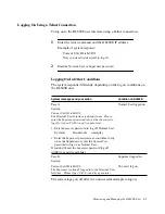
Page 39: ...e connected between DL600E units but it must not be connected to the terminal If you are using a cable not provided by Digital Link refer to Comm Port pin assignments in Appendix B To daisy chain mult...

Page 40: ...ormal User password you can Log on only when no one is logged on Be logged off by a Superuser The Superuser and Normal User passwords are set in Menu 8 Alarms II Refer to Con guring Two Levels of Acce...

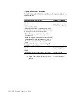
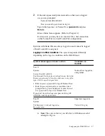
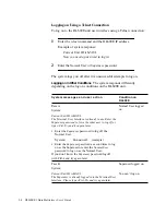
Page 41: ...ding on the log on conditions on the DL600E unit D Note The system forces you off after a fth unsuccessful attempt to log on System messages and user action Condition on DL600E Case A System Current U...

Page 42: ...messages and user action Condition on DL600E Case A System Current Unit ID is MAUI The Terminal User Interface is already in use Enter the Superuser password to force the other user to log off or type...

Page 43: ...a menu press the menu number as indicated at the bottom of the screen To redraw a screen press Ctrl L Setting a Parameter in a Menu Use the following method to select a parameter set it and con rm you...

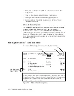
Page 44: ...s its status and con guration do not appear on the menu they reappear when the system responds Setting the Unit ID Date and Time Use Menu 4 Main Con guration to set the ID date and time SW Ver 1 0 MIB...

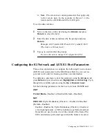
Page 45: ...ains how to con gure the following E1 network and AUX E1 port parameters for the DL600E unit Refer to your service provider work order for framing and line code information To con gure a parameter sel...

Page 46: ...clock source If the DL600E unit is the DTE device use a cable appropriate to your application When neither the Main nor Alternate clock source is available the DL600E unit uses INTERNAL During all ful...

Page 47: ...ervice and resets the system To download new software or update the download utility 1 Insert the new software diskette in the drive 2 From Menu 4 Main Con guration type f as instructed in the menu to...

Page 48: ...OK or BAD in the DOWNLOAD UTILITY menu DOWNLOAD UTILITY 0 1 Operational Software OK Updated Download Utility OK Factory Download Utility OK Download RAM allocated OK In the case of the rst three item...

Page 49: ...ader Code size xxx Corrupted Software Code size xxx checksum xxx Loader Load Received is the wrong load expected xxx received xxx Load Received has invalid embedded length Load Received is corrupted s...

Page 50: ...type 0 through 9 for a new menu Figure 3 3 Menu 5 Data Port Con guration The example in Figure 3 3 shows the local DL600E unit with four data ports in use The remote unit is a DL600E unit with one da...

Page 51: ...te unit in Menu 6 Timeslot Con guration according to your speci c needs and requirements Allocate by Port displays allocated timeslots for one data port at a time only Network Timeslot Map displays th...

Page 52: ...g 6 Timeslot Config 7 Alarm I 8 Alarm II 9 Diagnostics Type Arrow keys to move the selection RETURN to change a selection or type 0 through 9 for a new menu Figure 3 4 Menu 6 Timeslot Con guration In...

Page 53: ...Manually To manually allocate timeslots to a speci c data port move to the timeslot and specify the port You must set the other timeslots to Idle Timeslots for the AUX E1 port can only be allocated m...

Page 54: ...or B 3 Use the same method to con gure the other slots to IDLE 4 To con gure timeslots 3 7 9 13 and 15 for Data Port 1 Move to the speci c timeslot using the Arrows and press Return to activate edit...

Page 55: ...0 0 0 3rd NMS IP Address 0 0 0 0 0 0 0 0 Output Port COMM IBC Community Strings Get public public Set public public Trap public public 0 SNMP Config 1 Main Status 2 Data DTE Status 3 Reports 4 Main Co...

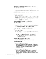
Page 56: ...The DL600E unit sends trap messages to this server TRAP 3rd NMS IP Address nnn nnn nnn nnn Default 0 0 0 0 nnn 0 through 255 Enter the IP address of the third Network Management Server The DL600E uni...

Page 57: ...passwords giving Superuser access to all users Assigning User Passwords It is important to specify unique Superuser and Normal User passwords in Menu 8 Alarms II Since two access methods to the DL600E...

Page 58: ...m to dial out if in Menu 8 Alarm II Connection is set to Modem valid telephone numbers are set in Phone Number 1 or Phone Number 2 How Alarms Reports Are Displayed Alarms are displayed on a terminal a...

Page 59: ...onditions to be reported default No Figure 3 6 shows an example of Menu 7 Alarm I SW Ver 1 0 Mib Ver 1 1 Digital Link DL600 Encore 9 06 94 HW Ver A Menu 7 Alarm I 12 56 56 Local ALADIN Remote JAFAR Bl...

Page 60: ...when a Network Sync Loss occurs NET UA1 Received Alarm Unframed All 1s Enabled Disabled Default Enabled Enabled The DL600E unit generates an alarm when it receives a UAI NET RAI Received Alarm Remote...

Page 61: ...and the DL600E unit action In the example in Figure 3 7 the remote unit can be a DL600E1 or a DL600E unit Table 4 2 DL600E Alarm Conditions and System Action Condition Action Loss of data port DL600E...

Page 62: ...onfig 1 Main Status 2 Data DTE Status Reports 4 Main Config 5 Data Port Config 6 Timeslot Config 7 Alarm I 8 Alarm II 9 Diagnostics Type Arrow keys to move the selection RETURN to change a selection o...

Page 63: ...in the menu only when the remote unit is a DL600E unit and applies only to it View only Normally Open Always Connection In Band Communications Modem Direct Default Direct Select the connection you are...

Page 64: ...tring Enter the login password for the Superuser 10 characters maximum D Note Refer to Con guring Two Levels of Access Rights earlier in this chapter COMM DCD Enabled or Disabled Default Disabled Enab...

Page 65: ...4 Monitoring and Managing the DL600E Unit Introduction 4 2 Logging on to the DL600E 4 2 Logging Off 4 6 Monitoring Status 4 6 Displaying Performance Reports 4 11...

Page 66: ...7 Alarm I and Menu 8 Alarm II Monitor the status of the E1 network AUX E1 port and data ports in Menu 1 Main Status and Menu 2 Data DTE Status respectively Monitor the E1 performance data base in Menu...

Page 67: ...ID to log on to it Press Ctrl x ve times to display all IDs of cards connected in a daisy chain a single RS 232 multidrop The default ID a six character alphanumeric is the DSU s portion of the serial...

Page 68: ...rface is already in use Please enter the Superuser password to force the other user to log off or type Ctrl X and try again later Normal User logged on Enter the Superuser password to log off the Norm...

Page 69: ...messages and your action Condition on DL600E Case A System Current Unit ID is MAUI The Terminal User Interface is already in use Please enter the Superuser password to force the other user to log off...

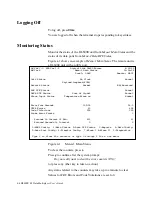
Page 70: ...AUX DTE Status Normal DATA DTE Status Loss of Signal Normal Alarm Input Status Temperature Alarm on Normal Error Free Seconds 100 0 96 5 CRC4 Errors 23 654 Code Violations 255 325 Frame Error Events...

Page 71: ...fraction Unit is sending User 1 pattern Send User 2 fraction Unit is sending User 2 pattern Send 1 1 fraction Unit is sending alternate 1s and 0s pattern Send 1 2 fraction Unit is sending standard loo...

Page 72: ...received set code Reset Code Received Unit has received reset code CV Threshold Exceeded CV Threshold exceeded CRC Threshold Exceeded CRC Threshold exceeded FE Threshold Exceeded FE Threshold exceede...

Page 73: ...the frame The calculation is performed again when the frame is received and the CRC values are compared If they do not match the frame is considered bad and the CRC statistic is incremented CodeViola...

Page 74: ...a DTE Status in which the remote unit can be either a SoloE1 Encore Ensemble Encore SoloE1 Shelf card or DL600E unit SW Ver 1 0 MIB Ver 1 2 Digital Link DL600 Encore 4 22 95 HW Ver A Menu 2 Data DTE S...

Page 75: ...ce Reports 12 40 12 Carrier Registers 24 hour detail Local OAHU Remote MAUI Local Interval Star ES CRC CV FE ES CRC CV 03 38 53 0 123 2 12 6 65 4 03 23 53 0 0 3 8 2 5 0 03 08 53 2 65 157 18 3 17 8 02...

Page 76: ...rored Seconds ES A second with one or more CRC errors Cyclic Redundancy Check CRC The CRC count is incremented in this error checking feature which compares frames at each end When the frames do not m...

Page 77: ...Interface Introduction 5 2 Preparing for the Initial Con guration 5 7 Con guring the Unit and Network Parameters 5 13 Allocating Timeslots 5 14 Con guring for SNMP 5 18 Using the MONITOR Menu 5 19 Us...

Page 78: ...the system s contents and organization is to use the terminal interface It displays the system in menus while the front panel interface displays only one line item at a time Use the front panel when a...

Page 79: ...most character of the display is an R No character appears on the local unit The front panel interface can be disabled only from the terminal interface using Protect Mode in Menu 4 Main Con guration H...

Page 80: ...ne menu item at a time appears in the 16 character uorescent display For example when you open the CONFIGURATION menu the UNIT CONFIG a submenu appears To see another submenu select it using the Up or...

Page 81: ...move down one menu level ENTER To move up one menu level EXIT To open a menu ENTER Editing Functions Front Panel Key To activate edit mode ENTER To execute a change in the con guration ENTER To exit...

Page 82: ...nk 3 Edit the ID one character at a time When the character is blinking use the Up or DownArrowkeyto cycle to the desired character and press ENTER to select the character If you do not wish to edit a...

Page 83: ...DL600E IP address and IP subnet mask for establishing a Telnet connection to the DL600E unit from a remote terminal and enabling SNMP network management capability One to three NMS IP addresses for e...

Page 84: ...o con gure the unit and network parameters respectively To open the CONFIGURATION menu use the Up or Down Arrows to move to the menu and press ENTER The UNIT CONFIG submenu appears The CONFIGURATION s...

Page 85: ...Date andTime Edit each item one character at a time To move to the next character press ENTER COMM PORT CONF submenu You can display and modify the Comm Port settings only from the front panel COMM P...

Page 86: ...meter appears for example UNIT ID HARRY_ 3 Select the COMM PORT CONF submenu using the Down Arrow and ENTER BAUD RATE 9600 appears Press ENTER to activate edit mode 9600 starts to blink 4 Cycle throug...

Page 87: ...IMING Enabling in NET IBC Changing the full bandwidth and fractional bandwidth loop codes in LPCODE and FLPCODE respectively These items are described in the following section Setting External Timing...

Page 88: ...detailed example of how to change network settings Example of Setting NetworkTiming In terminal mode the default setting for network timing is net INT in Main Alt Sync refer to Menu 4 Main Con guratio...

Page 89: ...LK and select a frequency for the external clock Enabling NET IBC You can enable IBC only by using the In Band Bit setting in the Network Con g menu Refer to Con guring the E1 Network Parameters in Ch...

Page 90: ...Press ENTER to activate edit mode RTS starts to blink Or press EXIT to take no action and move to the next item Press the Up or Down Arrows to cycle through the available LOS options and press ENTER t...

Page 91: ...To see the timeslot allocation for port 1 press the Up Arrow To see the allocation for port 2 press the Up Arrow again Repeat for the other ports if you have them Example The TIMESLOT CONFIG Menu The...

Page 92: ...allocation for port 1 to 1 through 15 to free the last 16 slots and allocate the slots to port 2 To allocate timeslots in a contiguous order 1 Open the TIMESLOT CONFIG menu by pressing ENTER The TS CO...

Page 93: ...change when prompted TO CHANGE CONFIG YES ENTER NO EXIT The timeslot allocation for port 2 appears Allocating Timeslots Manually in a Random Order Example To allocate timeslots in a random order Times...

Page 94: ...ENTER to open the display and ENTER again to activate edit mode for the port Press Up Arrow and ENTER to move to and select data port 2 3 Use this method to manually allocate each network timeslot to...

Page 95: ...he Network Manager Both the Monitor and Con guration Menus can also access the remote unit Remote monitoring and con guration are only available with an IBC In Band Communications channel attached to...

Page 96: ...he front panel display if the front panel is protected in Menu 4 Main Con guration UNIT Protect mode is enabled Only the Network Loopback test can be run on the remote unit from the TEST menu Starting...

Page 97: ...EST LED on the front panel turns green indicating the DL600E unit is out of service during the test The name of the current test appears on the display with a plus at the end You can open the MONITOR...

Page 98: ...me pattern from the remote unit It remains in this state until it achieves a lock or until you terminate the test When the DL600E unit achieves a lock with the signal from the remote unit it displays...

Page 99: ...the same pattern coming back from the remote unit The message PATTRN SEARCHING appears The test changes the DATA TEST LED from green to red to indicate a test is being performed on the port 5 When th...

Page 100: ...1 Select TEST PATTERN and press ENTER to open the menu 2 Use the Up or Down Arrow to cycle through the available options Press ENTER to open the TEST PTRN P1 or TEST PTRN P2 submenu TEST PATTERN ENTE...

Page 101: ...RN SEARCHING appears 5 When the DL600E unit achieves a lock with the signal from the remote unit it displays PATTRN 0 When it detects errors in the received pattern it displays the number of received...

Page 102: ...5 26 DL600E E1 Data Multiplexer User s Guide...
Page 103: ...6 Diagnosing the DL600E Unit Running Diagnostic Tests 6 2 The Diagnostics Menu 6 3 Test Parameters 6 4 Test Types 6 6 Running Tests from the Front Panel 6 10...

Page 104: ...o Using the TEST Menu in Chapter 5 for further information Refer to Chapter 3 for further information about connecting a terminal to the DL600E unit You can initiate the tests and loopbacks on the ful...

Page 105: ...Passed CRC4 Errors0 5 Code Violations0 5 18 Pattern Error Counter FractionFull Bandwidth DATA3 Test Length1 Min 15 Min TestLoop Payload DTE Loopback Full Bandwidth Loop CodeStandard Standard Fraction...

Page 106: ...Test Parameters This section describes the Menu 9 parameters and tests Menu 9 Diagnostics Parameters The parameters and options in the user selectable portion of Menu 9 Diagnostics are Fraction Full B...

Page 107: ...ote fraction NET Loopback full LP UP Remote fraction PLD Loopback fraction Lamp Test Send All 1s fraction Send All 0s fraction Send 1 1 fraction Send 1 2 fraction Send 1 4 fraction Send 1 7 fraction S...

Page 108: ...The PWR TEST LED blinks yellow and then turns green when the test is successful If the test fails the LED turns red for ten seconds and then green The possible messages are RUNNING SELF TEST SELF TES...

Page 109: ...m them if the test results indicate a phone company problem or require the DL600E unit to be removed from service Figure 6 2 Loop DTE Test Loop NET Test The Loop NET test veri es the operation of the...

Page 110: ...d Test Loop Up Remote and Loop Down Remote Tests The local DL600E unit puts the remote unit into network loopback by momentarily transmitting the industry standard loop up code to the remote unit If t...

Page 111: ...itors the signal for errors You can also use the QRW code to isolate an E1 network problem to a speci c transmission direction In this case both E1 transmission directions are monitored when the local...

Page 112: ...Remote test fails to terminate the remote loopback You can determine if the failure is an intermittent or hard failure by continuously sending the 1 2 and monitoring the network status to see if the p...

Page 113: ...Appendix A DL600E Technical Speci cations...

Page 114: ...erface optional Transmit line rate 2 048Mb s 50ppm Receive line rate 2 048Mb s 75ppm Line code HDB3 Data Rates Nx64kbps n 1 through 31 Framing ITU TS G 704 Input signal 0 to 7 dB0 Impedance 75W BNC un...

Page 115: ...000 ft ASL Reliability and Equipment Life MTBF 13 years minimum MTTR 30 minutes maximum Diagnostics and Tests Loopbacks E1 Network E1 Payload DTE Fractional E1 Payload Fractional DTE E1 Loopback Cont...

Page 116: ...grounding conductor serving the receptacle should be connected to earth ground at the service equipment Front Panel LEDs and Buttons Table A 1 describes the front panel LEDs buttons and connectors Ta...

Page 117: ...DATA TEST Port in normal or test modes Off Bandwidth not allocated NET Loopback Green Full Bandwidth Payload Loopback Green Fractional Payload Loopback on the fraction that belongs to the port Red Fr...

Page 118: ...Button brings the user to the Error Free Seconds display END TEST Buttons UPARROW DOWNARROW Pressing both buttons simultaneously to END TEST Move up to previous menu or option Move down to previous me...

Page 119: ...ata port Enabled Net Carrier Loss Alarm Enabled Net Sync Loss Alarm Disabled Net UA1 Received Alarm Enabled CV Threshold Alarm Disabled Net RAI Received Alarm Enabled CRC Threshold Alarm Disabled SNMP...

Page 120: ...1 User Pattern 2 Alarm Con guration Block All Alarms Loss of Signal from data port Net Carrier Loss Alarm Net Sync Loss Alarm Net UA1 Received Alarm CV Threshold Alarm Net RAI Received Alarm FE Thresh...

Page 121: ...DC 02 DL600E Base Unit with DC power supply 2 DTE ports DL600E DC 04 DL600E Base Unit with DC power supply 4 DTE ports DL600E DC 02D DL600E Base Unit with DC power supply 2 DTE ports and E1 Drop and I...

Page 122: ...A 10 DL600E E1 Data Multiplexer User s Guide...
Page 123: ...Appendix B Connector and Pin Assignments...

Page 124: ...s are listed in Table B 2 below Table B 1 Network Interface Pin Assignments Pin Signal 1 Send toward Network Tip T1 9 Send toward Network Ring R1 2 NC 3 Receive from Network Tip T 11 Receive from Netw...

Page 125: ...A B 17 9 Signal Element Timing 6 13 RT A B 8 26 Clock for RD RD changes on positive transition of SCR A SCR B Receive Data RD A B R T RD A B 3 16 Receive 4 11 RD A B 6 24 Received data from E1 networ...

Page 126: ...Equipment to DL600E Pin Assignments Name V 35 EIA 530 X 21 RS449 Description Send Data SD A B P S T D A B 2 14 Transmit 2 9 SD A B 4 22 Data stream from DTE to network Data Terminal Ready DTR H DTE R...

Page 127: ...37 RS449 DB25 Signal Name Signal 17 24 TT A To DTE 35 11 TT B To DTE 7 4 RS A From DTE 25 19 RS B From DTE 24 16 RD B To DTE 6 3 RD A To DTE 22 14 SD B From DTE 4 2 SD A From DTE 11 6 DM A To DTE 29 2...

Page 128: ...r the DB25 to V 35 DCE connector are listed below in Table B 6 Table B 6 DB25 to V 35 DCE Connector Pin Assignments Signal Name M 34 DB25 Signal Name Send Data S 16 Receive Data P 3 Receive Data T 14...

Page 129: ...37 RS449 DCE connector pin assignments Table B 7 DB25 to DC 37 RS449 DCE Connector Pin Assignments DC 37 RS449 DB25 Signal Name 8 24 A TT 26 11 B 13 4 A RTS 31 19 B 4 3 A RD 22 16 B 6 2 A SD 24 14 B...

Page 130: ...modem carrier drops with a user logged on the user is not logged out The DL600E unit continuously frees the modem screen repainting data and the modem does not answer dial in if receiving data Table B...

Page 131: ...0 DB25 to DE9 Adapter Pin Assignments Digital Link provides an adapter to accommodate the Digital Link DE9 Comm Port ribbon cable for the DB25 connector on the terminal port The pin out assignments ar...

Page 132: ...B 10 DL600E E1 Data Multiplexer User s Guide...
Page 133: ...for digital transmission services such as DDS and T1 in which the signal carrying the binary value successively alternates between positive and negative polarities Zero and one values are represented...

Page 134: ...lly with male or female components CPE Customer Premises Equipment Equipment that interfaces the tele phone network and physically resides at the user s location CRC Cyclic Redundancy Check A link lev...

Page 135: ...tions circuit The device being tested returns a received test message the results of which are compared to the original message DS0 Digital Signal Level 0 A 64kbit s standard digital telecommunication...

Page 136: ...ready for operation DTR Data Terminal Ready Signal from DTE to DSU CSU E E1 European counterpart to T1 which transmits at 2 048 Mbps 30 channels E2 European counterpart to T2 which transmits at 8 448...

Page 137: ...ay A high speed packet switching protocol used for wide area net works WANs faster than traditional X 25 networks because it is designed for today s reliable circuits and performs less rigorous error...

Page 138: ...ng through a data communications link or network This allows a technician or built in diagnostic circuit to compare the returned signal with the transmitted signal and get some sense of what s wrong L...

Page 139: ...tive and negative port The physical point of access into a computer network or other elec tronic device protocol A formal set of rules governing the format timing sequencing and error control of exch...

Page 140: ...ith high quality cable RS232 de nes the purpose and sig nal timing for each of the 25 lines however many applications use less than a dozen RS232 transmits positive voltage for a 0 bit negative voltag...

Page 141: ...th parallel port See RS232 serial transmission A sequential transmission of bits constituting an entity of data over a data circuit SG Signal Ground A signal from DTE to DSU CSU simplex current One wa...

Page 142: ...across remote distances T3 A digital carrier facility used to transmit a DS3 formatted digital signal at 44 736 Mbps T Carrier A time division multiplexed digital transmission facility usually operati...

Page 143: ...T standard 1976 for various loop back tests that can be incorporated into modems for testing the telephone cir cuit and isolating transmission problems Operating modes include local and remote digital...

Page 144: ...G 12 DL600E E1 Data Multiplexer User s Guide...
Page 145: ...community strings configuring for SNMP 3 21 configuring Solo Encore 3 30 configuring data port 3 16 for SNMP 3 21 network parameters 3 11 overview 3 9 CRC Errors 6 5 Menu 9 Diagnostics 6 3 threshold a...

Page 146: ...Payload test 6 8 Loss of signal on data port 3 16 M managing and monitoring Solo Encore 4 2 menus Menu 0 SNMP Con g 3 21 Menu 1 Main Status 4 6 Menu 2 Data DTE Status 4 10 Menu 5 Data Port Con gurati...

Page 147: ...T1 network port alarms 3 24 parameters 3 11 pin assignments B 2 telephone number dial out capability 3 30 Telnet 5 7 Telnet connection 1 4 2 3 3 6 3 23 4 2 terminal connecting through modem 3 4 inter...

Reviews: