6-6
DL600E E1 Data Multiplexer UserÕs Guide
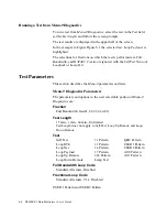
Test Types
Self Test
The
Self Test
checks the systemÕs electronic components and performs a
signal path check of the transmit and receive directions utilizing a
simulated
4000
foot (1220 meter)
E1
line.
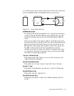
The test feeds a
QRW
test pattern to the transmitter circuit, passes it
through a simulated
E1
line back into the receiver, then feeds the test
pattern to the pattern detector circuit. When the code is successfully
detected, the
NET LED
turns on and the Power/Self Test
LED
turns
green. The
PWR/TEST LED
blinks yellow and then
turns green when the
test is successful. If the test fails, the
LED
turns red for
ten
seconds and
then green.
The possible messages are
RUNNING SELF TEST
SELF TEST PASSED
<N>
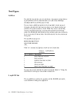
Table 4-1 contains descriptions of self test error indicators.
You can also run the
Self Test
from the front panel. Refer to ÒUsing the
TEST MenuÓ in Chapter 5 for further information.
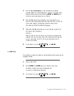
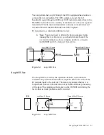
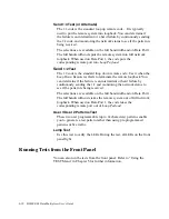
Loop DTE Test
The
Loop DTE
test veriÞes the operation of the DL600E unit and its
associated
DTE
cabling and equipment.
Table 4-1 Self Test Error
Indicators
Error indicators Description
0
ROM
Checksum test failed
1
RAM
test failed
2
EEPROM
Checksum test failed
3
DTE
test failed
4
Pattern test failed
5
Flash Proms Checksum test failed
Summary of Contents for DL600E
Page 1: ...DL600EE1 DataMultiplexer User s Guide...
Page 2: ......
Page 12: ...xiv DL600E E1 Data Multiplexer User s Guide...
Page 14: ...xvi DL600E E1 Data Multiplexer User s Guide...
Page 20: ...xxii DL600E E1 Data Multiplexer User s Guide...
Page 26: ...1 6 DL600E E1 Data Multiplexer User s Guide...
Page 34: ...2 8 DL600E E1 Data Multiplexer User s Guide...
Page 102: ...5 26 DL600E E1 Data Multiplexer User s Guide...
Page 113: ...Appendix A DL600E Technical Speci cations...
Page 122: ...A 10 DL600E E1 Data Multiplexer User s Guide...
Page 123: ...Appendix B Connector and Pin Assignments...
Page 132: ...B 10 DL600E E1 Data Multiplexer User s Guide...
Page 144: ...G 12 DL600E E1 Data Multiplexer User s Guide...

