background image

Digital Ally, Inc.  

|

  DVM Operation 

4-4

DVM-800 Operation Guide 

|

 860-00186-00 Rev L

Go Back To 

Table of Contents

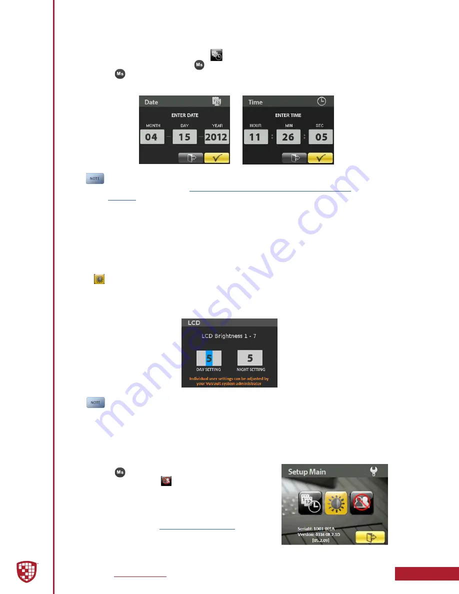
Setting the Date and Time 

To adjust the date or time, select the 

 icon from the Setup Main menu using the 

navigation button and press the

 button which opens the screen to adjust the setting. 

Press the

 button after the time or date have been adjusted to the desired setting. 

After the date and time have been set or changed, the DVM will reboot to apply the 

changes.

The date and time cannot be manually changed if “Clock Source” is configured 

for “GPS” in the VuVault  

Admin > Devices > DVM-800 Settings > General > 

Location

 Menu.

Adjusting LCD Brightness 

The global default LCD brightness settings are configured using the 

VuVault > Devices > 

DVM-800 Settings > Display

 menu. These settings can also be configured for each user 

individually by the Administrator using the VuVault software. 

To temporarily override the day/night brightness values configured in VuVault, select 

the 

 icon from the 

Setup Main

 menu screen. Use the arrow keys on the front of the 

DVM to change the brightness settings for both day and night mode. A sensor on the 

front of the DVM automatically detects the ambient light level and places the LCD 

display in the correct mode.

Brightness settings will remain in effect until the next power cycle. We 

recommend that each user experiment with the brightness settings and 

decide which work best, then provide this information to your VuVault system 

administrator. The administrator can then configure the default brightness 

settings for each user.

Logging out of the DVM

Press the

 button to access the Setup Main menu 

screen, then select the   option to log out of the 

system. You will then be presented with the log in 

screen for you or another user to log back into the 

system.  

When logging out, the 

default configuration 

and 

parameters will be loaded until the next user logs into 

the system.

Summary of Contents for DVM-800

Page 1: ...ed This publication may not be repro duced stored in a retrieval system or transmitted in whole or part in any form or by any means electronic mechanical recording photocopying or in any other manner...

Page 2: ...ce 3 3 Daylight Saving 3 3 Time Format 3 3 Display 3 4 LCD Brightness 3 4 Record LED Behavior 3 4 LCD Mode 3 4 Power 3 5 Ignition Shutdown Timer 3 5 Days in LPS Low Power Standby 3 5 Settings 3 6 Audi...

Page 3: ...3 21 USB Port 3 21 3 10 GPS 3 21 GPS Locations 3 21 Latitude degrees 3 21 Longitude degrees 3 21 Max Distance 3 22 Locations of Interest 3 22 Time in Location 3 22 Latitude 3 22 Longitude 3 22 Radius...

Page 4: ...emote Accessory Control 5 3 5 11 Muting the Wireless Microphone Audio 5 3 5 12 Muting the Audio for the In Car Microphone 5 3 Section 6 Event Recording Management 6 1 6 1 Video Playback and Management...

Page 5: ...Pre Event recording will capture up to 30 seconds prior to the start of a recording Pre Event Record time is adjustable in 6 second increments Records metadata with the audio and video including devic...

Page 6: ...LCD brightness 8 Menu and Playback Buttons Used to navigate the DVM menus play back videos and log into the system 9 External SD Card A removable SD card is installed behind the external SD door The...

Page 7: ...m the new configuration file The old configuration settings will be overwritten and discarded Once the update process has started Do not remove power Do not turn the ignition off Do not remove the ext...

Page 8: ...DESIRED SETTINGS HAVE BEEN ENTERED CLICK SAVE AND PROCEED TO SECTION 3 11 TO ACTIVATE YOUR SD CARD 3 1 Default Configuration If the unit has never been activated it will use the following default sett...

Page 9: ...ated on the back of the DVM and type it into the wizard do not include the hyphen Assign it a name and description When done press Save For more information consult the VuVault Administrator Guide Add...

Page 10: ...date format displayed on the event recordings is selected through this setting Settings mm dd yy default yy mm dd dd mm yy Clock Source Choose to receive the time setting automatically through the GP...

Page 11: ...how the LCD screen will operate during pre event and during recorded events Consult the table below Settings Off On Auto default Table 3 4 Choosing your display behavior Setting LCD Behavior ON LCD wi...

Page 12: ...or Ignition Shutdown Timer and then the operation for Days in LPS configuration The Days in LPS configuration specifies the number of consecutive days the DVM will remain in Low Power Standby before c...

Page 13: ...out from no user input This timer applies to the Main Menu and Profile screens When the timer has expired the DVM will return to standby mode Settings 0 to 600 seconds default 60 seconds 3 4 Profile C...

Page 14: ...includes an external 32GB SD card which is used as the primary memory storage Use the following options in this section to configure your record settings Record Quality The Record Quality parameter a...

Page 15: ...rs 27 6 hours Standard 15fps 6MB 82 8 hours 41 4 hours Standard 10fps 4MB 124 0 hours 62 0 hours Standard 5fps 3MB 164 4 hours 82 2 hours File size varies with the Record Quality FPS settings and vide...

Page 16: ...rding While the DVM is wirelessly transferring files The video playback screen is on or video is being played on the DVR ECA will always record in Loop mode When the Internal Memory is completely fill...

Page 17: ...desired Consult Section 3 8 to review your IF Box input sensor configuration Source 1 Select the camera that will be recorded on video channel 1 This camera will also be available for display on the D...

Page 18: ...bility to display and record radar information in a video recording Use the Radar section to configure the settings for the specific type of radar that is used Radar Type Select the model of the radar...

Page 19: ...rnering collision and vertical movements Accelerometer event triggers can be disabled by setting the G force levels to zero 0 in the configuration of the DVM Setting the G force level greater than zer...

Page 20: ...ource the Sensor 4 settings will automatically be configured as an Event Trigger as shown in the IF Box Input Sensors screen below The IF Box Sensor 4 input wire must be connected to the Vehicle Speed...

Page 21: ...for extending the CAN bus to other Digital Ally devices IF Box Input Sensors The Interface Box has six multi purpose input sensors which must be configured in the DVM for proper operation The input s...

Page 22: ...igger state to the trigger activated state Refer to figure 3 17a for more information Settings Low to High default Attached device is triggered by going from low voltage to high voltage High to Low At...

Page 23: ...ive external sensor Setting LCD Behavior ON Source 1 LCD displays live video from Channel 1 while Event Camera Source 1 is active Pressing while two channels are recording will toggle the display betw...

Page 24: ...direction for the Detection Type then select the Threshold setting nearest to the triggered state The figure below illustrates these steps Figure 3 17a Detection and Threshold Parameters for Input Sen...

Page 25: ...tion The Detection Threshold parameters displayed above assumes your reverse gear signal is 0v non active and 12VDC active If the reverse gear signal for your vehicle is different you will need to con...

Page 26: ...situation where Sensor Only sensors could override the Camera switching LCD control and Output Alarm control for an Event Trigger type sensor Output Alarm The IF Box Output Alarm signal is used to co...

Page 27: ...fined in the Data Transfer Network WTM Settings and automatically upload event recordings and files To enable the wireless function choose either Basic or Advanced Choose None if you will not be using...

Page 28: ...used with the Wi Fi adapter for wireless functionality This parameter determines if the DVM USB port for data connections to a PC is enabled or disabled Wi Fi adapter connectivity is not affected by t...

Page 29: ...w are the configurable items Time in Location Enter the allowable time in this location before an event recording is triggered days hours and minutes The minimum time in a location of interest before...

Page 30: ...CE This can be changed according to customer preference to whatever is deemed most appropriate 7 Choose from one of four options to activate the card Activate Device Leave Data Intact Activates the ca...

Page 31: ...Recording in Progress Upper Channel 1 Lower Channel 2 Standby Pre Event Enabled Upper Channel 1 Lower Channel 2 Standby Pre event Disabled 11 15 16 Lower left Date mm dd yy 08 47 55 Lower left Time of...

Page 32: ...sert first check the card slot for obstructions and ensure that the card orientation is correct then try inserting the card again The SD card may be removed when the DVM is powered Off or in Standby m...

Page 33: ...he Setup Main Menu screen Viewing Current Configuration Press the button to access the Setup Main menu screen then navigate to highlight the Serial and Version section Press the button to view the cur...

Page 34: ...r using the VuVault software To temporarily override the day night brightness values configured in VuVault select the icon from the Setup Main menu screen Use the arrow keys on the front of the DVM to...

Page 35: ...button will increase the zoom magnification level by 1x Press and hold to zoom in faster Each quick press and release of the ZOOM OUT button will decrease the zoom magnification level by 1X Press and...

Page 36: ...are pressed within the configured Entry Timout period the unit will return to Standby mode Place Marks in a Recording Once a recording has been initiated markers can be placed in the recording to ind...

Page 37: ...s than 16 characters the entire Incident ID can be displayed Press and release the button to exit the playback list Playback Control During playback audio is played through the built in speaker and vo...

Page 38: ...e DVM is actively transferring video files to your computer A VuVault Wireless Server must be configured to use the wireless transfer feature see Section 7 and the VuVault Wireless Server Setup Guide...

Page 39: ...ogether If the Transmitter was paired to another Cradle it will no longer respond to previous Cradle pairing The pairing operation only needs to be performed the first time a system is used or a new T...

Page 40: ...tandby mode re enter normal range and press the REC button Operation will return to normal If you will be out of range for a long period of time turn the Transmitter off 5 6 Charging Information The T...

Page 41: ...smitter next to the Low Batt indicator a beep will sound and the Remote Accessory output will activate Press the Remote Accessory button again on the transmitter a beep will sound and the Remote Acces...

Page 42: ...ftware package which allows the organization and playback of DVM 800 video audio and metadata files It also offers many advanced features such as GPS mapping security groups generating reports printin...

Page 43: ...e is required for wireless file transfer Basic In Basic Wi Fi mode after the event files have been uploaded to the server the DVM will delete the files from DVM s primary memory storage This mode prov...

Page 44: ...ode Off Off Off Standby or Standby Pre Event Off On Reflects the state of audio recording Audio Record enabled Event Record or Pre event Reflects the state of video recording On On SD card has been re...

Page 45: ...nsions 48mm 1 9in D x 279mm 11in W x 106mm 4 7in H Weight 733g 1 62lbs Internal Components LCD Monitor 3 5 Color Ultra Bright 640x480 resolution Real Time Clock On board used when GPS signal is lost A...

Page 46: ...LEDs OFF 0 0 Lux with IR LED s ON Internal Passenger Facing Camera Resolution D1 FOV 96 V X 119 H X 141 D Focus Fixed lens IR LED assisted for low light conditions 0 5 Lux with IR LEDs OFF 0 0 Lux wi...

Page 47: ...g Battery Internal Li ion 3 7V 1800mAh cell 20 hours In Use with full charge 14 days Standby 4 hours charge time Frequency DWM 928 900MHz FHSS 50 possible channels DWM 868 800MHz FHSS 50 possible chan...

Page 48: ...move the SD card Place it in a card reader connected to your computer 3 Copy the unzipped file from your computer to the SD Card 4 Using the removable media feature of the computer system safely remov...

Page 49: ...WTM Lite 4 Click Update Devices 5 Select the Deploy Update Files button 6 Using the navigation window point to the location where the firmware l file is located Select the file and click Open 7 Place...

Page 50: ...ed in the in line fuse housing on the power cable 3 Verify there are no breaks pinches or cuts in the wiring or cable harness 4 Check the wiring and voltage levels to the vehicle power and ignition sw...

Page 51: ...2 Verify the reverse gear wiring is connected to corresponding input sensor as defined in the device configuration 3 Verify the Reverse Gear signal voltages 4 Verify there are no breaks pinches or cu...

Page 52: ...or raise the accelerometer trigger level value 4 Verify external sensor configuration is correct for actual external device connected Improper wiring or improper configurations may cause false trigge...

Page 53: ...ts off Failed to Mount Primary Memory Failed to mount primary memory before starting recording Blank screen with error text then DVM shuts off 10 6 Performing a Reset Using a small device such as a pa...

Page 54: ...unit carelessness unauthorized alterations to the unit improper storage of the unit or unauthorized service installation or repairs made to the unit Damage caused by fire flood lightning vandalism co...

Page 55: ...al device pursuant to Part 15 of the FCC Rules These limits are designed to provide reasonable protection against harmful interference when the equipment is operated in a commercial environment This e...

Page 56: ...00 Rev L Go Back To Table of Contents 9705 Loiret Blvd Lenexa KS 66219 w www digitalallyinc com p 913 814 7774 f 913 814 7775 Support E mail support digitalallyinc com Sales E mail sales digitalallyin...

Reviews: