Digital Ally, Inc.
|
Device Configuration
3-18
DVM-800 Operation Guide
|
860-00186-00 Rev L
How to Configure a Backup Camera
The DVM-800 can provide a backup camera image on the LCD when the vehicle is
shifted into reverse gear. In addition, the DVM-800 can be configured to record the
backup event. An optional backup camera or license plate camera kit is required.
The backup camera is connected to the DVM CAM2 input.
The vehicle’s reverse gear
signal must be connected to Sensor Input #1 of the IF Box
(consult the
“DVM-800
Installation Guide”
for more information).
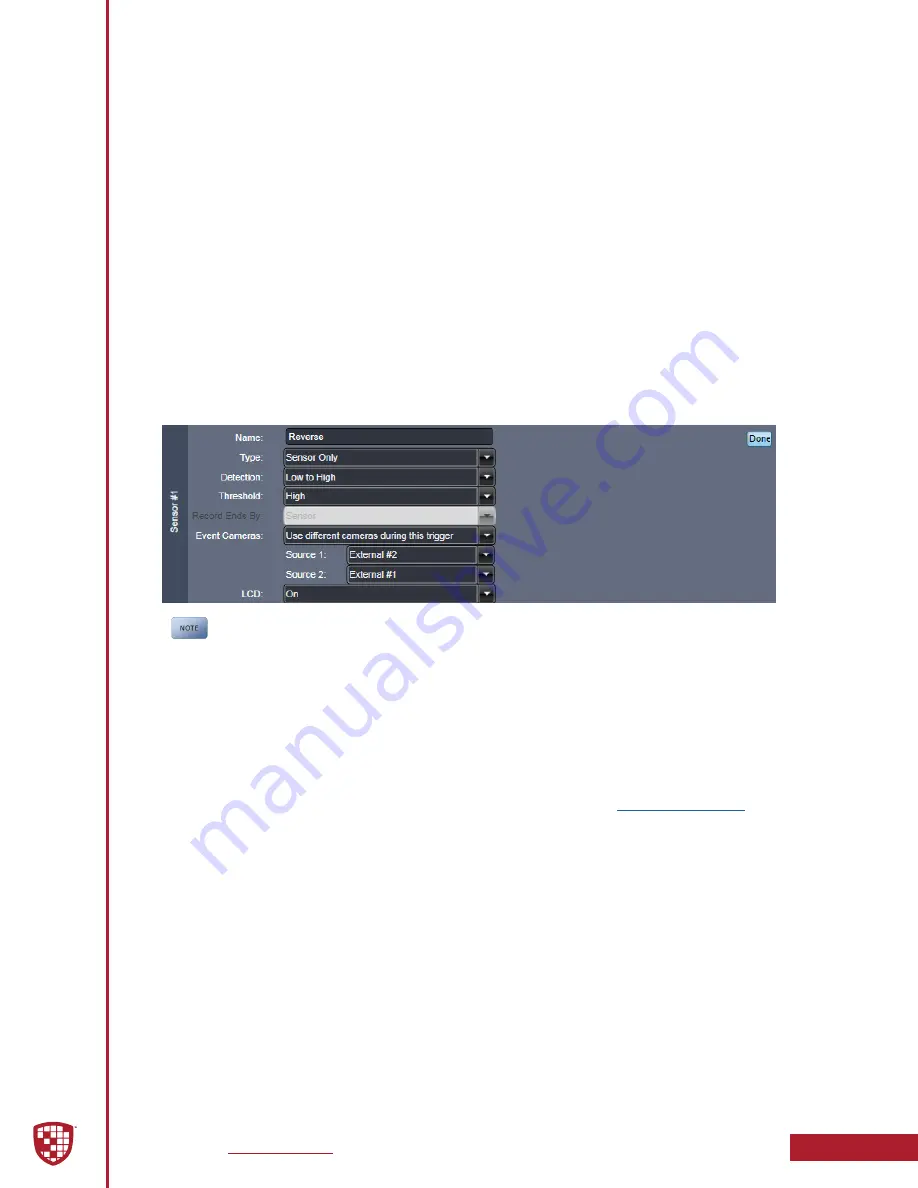
The example below illustrates a typical backup camera configuration. Using this
example, your DVM-800 will display the backup camera image on the LCD whenever the
reverse gear is active, but will not start a recorded event. When recording the Backup
Camera Event is not required, configure the
Type
for Sensor #1 as
“Sensor Only”
. If
recording the backup camera event is required, configure the Type for Sensor #1 as
“Event Trigger”
. The LCD can be configured to turn ON or OFF in either mode, or to take
“No Action”
. Note that
Source 1
is configured for
External #2
, and
LCD
is set to ON. After
you have made your selections, select
Done
.
Figure 3-18:
Sample Reverse Gear Configuration
The Detection & Threshold parameters displayed above assumes your reverse
gear signal is 0v (non-active) and 12VDC (active). If the reverse gear signal
for your vehicle is different, you will need to configure the DVM for proper
operation in your vehicle using the “Detection & Threshold Parameter” table
on the previous page.
Reverse Record Override
By default, the reverse gear camera selections will take priority over other sensors
and record triggers whenever the vehicle is in reverse. The reverse camera source will
override the default
Source 1
camera selection configured in the
Menu. Once the reverse trigger becomes inactive, the original camera image source
will be displayed once again. If the reverse trigger is active when the recording ends,
the backup camera image will continue to display. To change this behavior, move the
reverse sensor down on the event priority list.
Event Priority
The
Event Priority
list defines the LCD control, camera switching, and Output Alarm
control when multiple triggers and/or sensors are simultaneously active. There are
eight categories for prioritization which include:
IF Box Sensors 1 through 6
,
Internal
Events
, and
Pre-event
. Using the VuVault
®
software, drag and drop your named sensor
blocks to set the camera, LCD, and output alarm priority. The
Event Priority
rules are
defined as highest to lowest from left to right.
•
Sensors 1 through 6
as configured in the
Sensor
tab of the VuVault
software.


