2
BASIC SETUP
1. Connect the Cameras
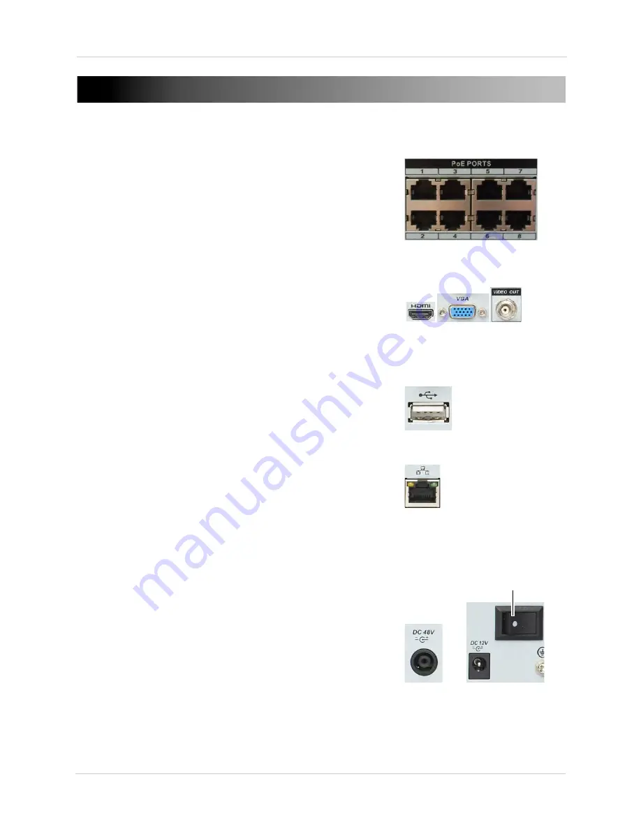
a. Connect IP cameras to PoE (Power over Ethernet)
ports.
OR
b. Connect IP cameras to the same LAN as the NVR. For
details on connecting IP cameras over the LAN, see
“Device Search” on page 31.
2. Connect a Monitor
a. Connect an HDMI cable (not included) from the HDMI
port on the rear panel to an HDTV or HDMI monitor.
OR
b. Connect a VGA cable (not included) from the VGA port
to the VGA port on your monitor.
OR
c. Connect a BNC terminated cable (not included) from
the Video OUT port to a TV or CCTV monitor.
3. Connect the Mouse
a. Connect the mouse (included) to the USB mouse port
on the front or rear panel.
4. Connect the Ethernet Cable
a. Connect an Ethernet cable (not included) to the LAN
port on the rear panel of system; connect the other end
of the Ethernet cable to an empty LAN port on your
router or switch (not included).
5. Connect the Power Adapters
a. Connect the DC 12V power supply to the DC 12V port on
the rear panel of the system. Connect the power cable
to an outlet, power strip, or surge protector. This power
adapter is used to power the main unit.
b. Connect the DC 48V power supply to the DC 48V port on
the rear panel of the system. Connect the power cable
to an outlet, power strip, or surge protector. This power
adapter is used to power the integrated PoE ports.
c. Turn the power switch to the ON position.
Connect IP cameras to the system
Connect to an HDMI, VGA, or BNC monitor
Connect an Ethernet cable
Connect the mouse to a USB port
Connect the power adapters
ON
Summary of Contents for DNR200 Series
Page 49: ...39 Using the Main Menu...


