15
EN
6. In the case of hydraulic connections between tractor and implement, it is advisable to mark the
coupling sleeves and plugs to avoid any incorrect connections!
Should the connections be confused, the function is reversed (e.g. raising/lowering). Danger of
accidents!
7.
Hydraulic oil forced out under high pressure can break the skin and cause severe damage! In the
case of injury, report to a doctor immediately as there is a risk of infection!
1.8.5 Tyres
1.
Prior to working on the tyres, make sure the Rotary Tedder is standing safely and secured against
rolling away! Wheel chocks!
2. The fitting of tyres and wheels presupposes sufficient knowledge as well as the availability of all
necessary tools!
3. Only skilled workers using appropriate tools may repair or mount tyres and wheels!
4. Check the inflation pressure at regular intervals. Observe the prescribed inflation pressure!
1.9
Safety when implement is not in use or is in storage
1.
Store the Rotary Tedder in a safe place.
2. Make sure that no children play on or around the Rotary Tedder.
3. Only couple or uncouple the Rotary Tedder on firm, dry and level ground. This minimizes the
danger of the implement tipping, or sinking into the soft ground or mud.
4. Place the detached cardan shaft onto its support!
5. Use wheel chocks to prevent the Rotary Tedder from rolling away.
6. Only park the Rotary Tedder with the rotary unit lowered (danger of tipping, injury from tines)!
1.10 Maintenance
Directions quoted ("right", "left", "in front","behind") are always taken as being in the direction of travel.
The direction of rotation is defined as follows:
z
Direction of rotation right = clockwise,
z
Direction of rotation left = anticlockwise,
z
Rotations around a vertical axis, taken from top to bottom,
z
Rotations around a horizontal axis, at a right angle to the direction of travel, taken from left to
right,
z
Rotations of nuts, bolts etc. are always taken from the side from which they are operated.
Summary of Contents for CondiMaster 6831
Page 2: ......
Page 4: ...2 EN...
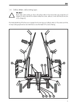
Page 13: ...11 EN 6 Keep clear of the swivel area of the implement...
Page 33: ...31 EN 40 h 8 h 40 h 40 h 8 h 8 h 16 h 40 h Fig 5 1 Fig 5 2...
Page 37: ......


