


If you enable VLT unicast routing, the following actions occur:
• L3 routing is enabled on any new IP address / IPv6 address configured for a VLAN interface that is up.
• L3 routing is enabled on any VLAN with an admin state of up.
NOTE: If the CAM is full, do not enable peer-routing.
NOTE: The peer routing and peer-routing-timeout is applicable for both IPv6/ IPv4.
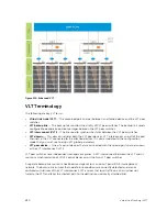
Configuring VLT Unicast
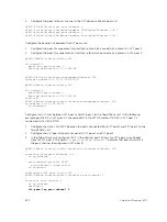
To enable and configure VLT unicast, follow these steps.
1.
Enable VLT on a switch, then configure a VLT domain and enter VLT-domain configuration mode.
CONFIGURATION mode
vlt domain
domain-id
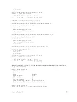
2.
Enable peer-routing.
VLT DOMAIN mode
peer-routing
3.
Configure the peer-routing timeout.
VLT DOMAIN mode
peer-routing—timeout
value
value
: Specify a value (in seconds) from 1 to 65535. The default value is infinity (without configuring
the timeout).
VLT Multicast Routing
VLT Multicast Routing provides resiliency to multicast routed traffic during the multicast routing protocol
convergence period after a VLT link or VLT peer fails using the least intrusive method (PIM) and does not
alter current protocol behavior.
Unlike VLT Unicast Routing, a normal multicast routing protocol does not exchange multicast routes
between VLT peers. When you enable VLT Multicast Routing, the multicast routing table is synced
between the VLT peers. Only multicast routes configured with a Spanned VLAN IP as their IIF are synced
between VLT peers. For multicast routes with a Spanned VLAN IIF, only OIFs configured with a Spanned
VLAN IP interface are synced between VLT peers.
The advantages of syncing the multicast routes between VLT peers are:
•
VLT resiliency
— After a VLT link or peer failure, if the traffic hashes to the VLT peer, the traffic
continues to be routed using multicast until the PIM protocol detects the failure and adjusts the
multicast distribution tree.
•
Optimal routing
— The VLT peer that receives the incoming traffic can directly route traffic to all
downstream routers connected on VLT ports.
•
Optimal VLTi forwarding
— Only one copy of the incoming multicast traffic is sent on the VLTi for
routing or forwarding to any orphan ports, rather than forwarding all the routed copies.
Important Points to Remember
• You cannot configure a VLT node as a rendezvous point (RP), but any PIM-SM compatible VLT node
can serve as a designated router (DR).
860
Virtual Link Trunking (VLT)
Summary of Contents for Z9000
Page 1: ...Dell Configuration Guide for the Z9000 System 9 7 0 0 ...
Page 80: ...grub reboot 80 Management ...
Page 128: ... 0 Te 1 1 Te 1 2 rx Flow N A N A 128 Access Control Lists ACLs ...
Page 491: ...Figure 70 Configuring OSPF and BGP for MSDP Multicast Source Discovery Protocol MSDP 491 ...
Page 496: ...Figure 73 MSDP Default Peer Scenario 1 496 Multicast Source Discovery Protocol MSDP ...
Page 497: ...Figure 74 MSDP Default Peer Scenario 2 Multicast Source Discovery Protocol MSDP 497 ...
Page 498: ...Figure 75 MSDP Default Peer Scenario 3 498 Multicast Source Discovery Protocol MSDP ...
Page 760: ...Figure 100 Single and Double Tag TPID Match 760 Service Provider Bridging ...
Page 761: ...Figure 101 Single and Double Tag First byte TPID Match Service Provider Bridging 761 ...


