
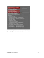


When you use NIC teaming, consider that the server MAC address is originally learned on Port 0/1 of the
switch (shown in the following) and Port 0/5 is the failover port. When the NIC fails, the system
automatically sends an ARP request for the gateway or host NIC to resolve the ARP and refresh the egress
interface. When the ARP is resolved, the same MAC address is learned on the same port where the ARP is
resolved (in the previous example, this location is Port 0/5 of the switch). To ensure that the MAC address
is disassociated with one port and re-associated with another port in the ARP table, configure the
mac-
address-table station-move refresh-arp
command on the Dell Networking switch at the time
that NIC teaming is being configured on the server.
NOTE: If you do not configure the
mac-address-table station-move refresh-arp
command, traffic continues to be forwarded to the failed NIC until the ARP entry on the switch
times out.
Figure 56. Configuring the mac-address-table station-move refresh-arp Command
Configure Redundant Pairs
Networks that employ switches that do not support the spanning tree protocol (STP) — for example,
networks with digital subscriber line access multiplexers (DSLAM) — cannot have redundant links
between switches because they create switching loops (as shown in the following illustration). The
redundant pairs feature allows you to create redundant links in networks that do not use STP by
configuring backup interfaces for the interfaces on either side of the primary link.
NOTE: For more information about STP, refer to
.
Assign a backup interface to an interface using the
switchport backup
command. The backup
interface remains in a Down state until the primary fails, at which point it transitions to Up state. If the
primary interface fails, and later comes up, it becomes the backup interface for the redundant pair. Dell
Networking OS supports Gigabit, 10 Gigabit, and 40-Gigabit interfaces as backup interfaces.
452
Layer 2
Summary of Contents for Z9000
Page 1: ...Dell Configuration Guide for the Z9000 System 9 7 0 0 ...
Page 80: ...grub reboot 80 Management ...
Page 128: ... 0 Te 1 1 Te 1 2 rx Flow N A N A 128 Access Control Lists ACLs ...
Page 491: ...Figure 70 Configuring OSPF and BGP for MSDP Multicast Source Discovery Protocol MSDP 491 ...
Page 496: ...Figure 73 MSDP Default Peer Scenario 1 496 Multicast Source Discovery Protocol MSDP ...
Page 497: ...Figure 74 MSDP Default Peer Scenario 2 Multicast Source Discovery Protocol MSDP 497 ...
Page 498: ...Figure 75 MSDP Default Peer Scenario 3 498 Multicast Source Discovery Protocol MSDP ...
Page 760: ...Figure 100 Single and Double Tag TPID Match 760 Service Provider Bridging ...
Page 761: ...Figure 101 Single and Double Tag First byte TPID Match Service Provider Bridging 761 ...


