


Apply all other configurations to each interface in the redundant pair such that their configurations are
identical
, so that transition to the backup interface in the event of a failure is transparent to rest of the
network.
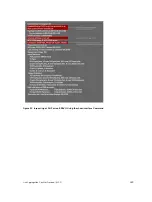
Figure 57. Configuring Redundant Layer 2 Pairs without Spanning Tree
You configure a redundant pair by assigning a backup interface to a primary interface with the
switchport backup interface
command. Initially, the primary interface is active and transmits traffic
and the backup interface remains down. If the primary fails for any reason, the backup transitions to an
active Up state. If the primary interface fails and later comes back up, it remains as the backup interface
for the redundant pair.
Dell Networking OS supports only Gigabit, 10 Gigabit, and 40-Gigabit ports and port channels as primary/
backup interfaces in redundant pairs. (A port channel is also referred to as a link aggregation group (LAG).
For more information, refer to
) If the interface is a member link of a LAG, the following
primary/backup interfaces are also supported:
• primary interface is a physical interface, the backup interface can be a physical interface
• primary interface is a physical interface, the backup interface can be a static or dynamic LAG
• primary interface is a static or dynamic LAG, the backup interface can be a physical interface
• primary interface is a static or dynamic LAG, the backup interface can be a static or dynamic LAG
In a redundant pair, any combination of physical and port-channel interfaces is supported as the two
interfaces in a redundant pair. For example, you can configure a static (without LACP) or dynamic (with
Layer 2
453
Summary of Contents for Z9000
Page 1: ...Dell Configuration Guide for the Z9000 System 9 7 0 0 ...
Page 80: ...grub reboot 80 Management ...
Page 128: ... 0 Te 1 1 Te 1 2 rx Flow N A N A 128 Access Control Lists ACLs ...
Page 491: ...Figure 70 Configuring OSPF and BGP for MSDP Multicast Source Discovery Protocol MSDP 491 ...
Page 496: ...Figure 73 MSDP Default Peer Scenario 1 496 Multicast Source Discovery Protocol MSDP ...
Page 497: ...Figure 74 MSDP Default Peer Scenario 2 Multicast Source Discovery Protocol MSDP 497 ...
Page 498: ...Figure 75 MSDP Default Peer Scenario 3 498 Multicast Source Discovery Protocol MSDP ...
Page 760: ...Figure 100 Single and Double Tag TPID Match 760 Service Provider Bridging ...
Page 761: ...Figure 101 Single and Double Tag First byte TPID Match Service Provider Bridging 761 ...


