


VLAN ID
: The VLAN identification of the control VLAN.
4.
Configure the Master node.
CONFIG-FRRP mode.
mode
master
5.
Identify the Member VLANs for this FRRP group.
CONFIG-FRRP mode.
member-vlan
vlan-id
{
range
}
VLAN-ID, Range
: VLAN IDs for the ring’s member VLANS.
6.
Enable FRRP.
CONFIG-FRRP mode.
no disable
Configuring and Adding the Member VLANs
Control and member VLANS are configured normally for Layer 2. Their status as Control or Member is
determined at the FRRP group commands.
For more information about configuring VLANS in Layer 2 mode, refer to the
Be sure to follow these guidelines:
• All VLANS must be in Layer 2 mode.
• Tag control VLAN ports. Member VLAN ports, except the Primary/Secondary interface, can be tagged
or untagged.
• The control VLAN must be the same for all nodes on the ring.
To create the Members VLANs for this FRRP group, use the following commands on all of the Transit
switches in the ring.
1.
Create a VLAN with this ID number.
CONFIGURATION mode.
interface vlan
vlan-id
VLAN ID: the range is from 1 to 4094.
2.
Tag the specified interface or range of interfaces to this VLAN.
CONFIG-INT-VLAN mode.
tagged
interface slot/port
{
range
}
Interface
:
•
Slot/Port
: Slot and Port ID for the interface. Range is entered Slot/Port-Port
Slot/Port
.
• For a 10-Gigabit Ethernet interface, enter the keyword
TenGigabitEthernet
then the slot/port
information.
• For a 40-Gigabit Ethernet interface, enter the keyword
fortyGigE
then the slot/port
information.
3.
Assign the Primary and Secondary ports and the Control VLAN for the ports on the ring.
CONFIG-FRRP mode.
284
Force10 Resilient Ring Protocol (FRRP)
Summary of Contents for Z9000
Page 1: ...Dell Configuration Guide for the Z9000 System 9 7 0 0 ...
Page 80: ...grub reboot 80 Management ...
Page 128: ... 0 Te 1 1 Te 1 2 rx Flow N A N A 128 Access Control Lists ACLs ...
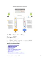
Page 491: ...Figure 70 Configuring OSPF and BGP for MSDP Multicast Source Discovery Protocol MSDP 491 ...
Page 496: ...Figure 73 MSDP Default Peer Scenario 1 496 Multicast Source Discovery Protocol MSDP ...
Page 497: ...Figure 74 MSDP Default Peer Scenario 2 Multicast Source Discovery Protocol MSDP 497 ...
Page 498: ...Figure 75 MSDP Default Peer Scenario 3 498 Multicast Source Discovery Protocol MSDP ...
Page 760: ...Figure 100 Single and Double Tag TPID Match 760 Service Provider Bridging ...
Page 761: ...Figure 101 Single and Double Tag First byte TPID Match Service Provider Bridging 761 ...


