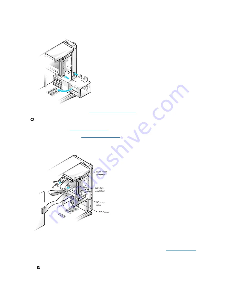
Installing the Hard-Drive Bracket in the Chassis
9.
Connect the interface cable for the drive (see "
Attaching Hard Drive Cables in the Chassis
").
a.
If you are installing an EIDE device, ensure that the IDE interface cable is properly connected to the EIDE connector on the system board. For
more information, see "
EIDE Device Installation Guidelines
."
b.
If you are installing a SCSI device, ensure that the SCSI interface cable is properly connected to the interface connector on the SCSI controller
board. For more information, see "
SCSI Device Installation Guidelines
."
10.
Connect a DC power cable to the power input connector on the back of the drive (see the following figure).
Attaching Hard Drive Cables in the Chassis
11.
Ensure that all cables are firmly connected. Fold cables out of the way to provide airflow for the fan and cooling vents.
12.
Ensure that the control panel cable is firmly connected to the system board.
The control panel contains the hard-drive activity indicator. To locate the control panel system board connector, see "
System Board Components
."
13.
Replace the front panel.
14.
Replace the computer cover, reconnect the computer and peripherals to their electrical outlets, and turn them on.
ALERT! Cover was previously removed.
NOTICE:
To avoid possible damage, you must match the colored strip on the interface cable with pin 1 on both the drive and system board connectors.
NOTE:
If enabled, the
Chassis Intrusion
option will cause the following message to be displayed at the next system start-up:


