background image

Steps

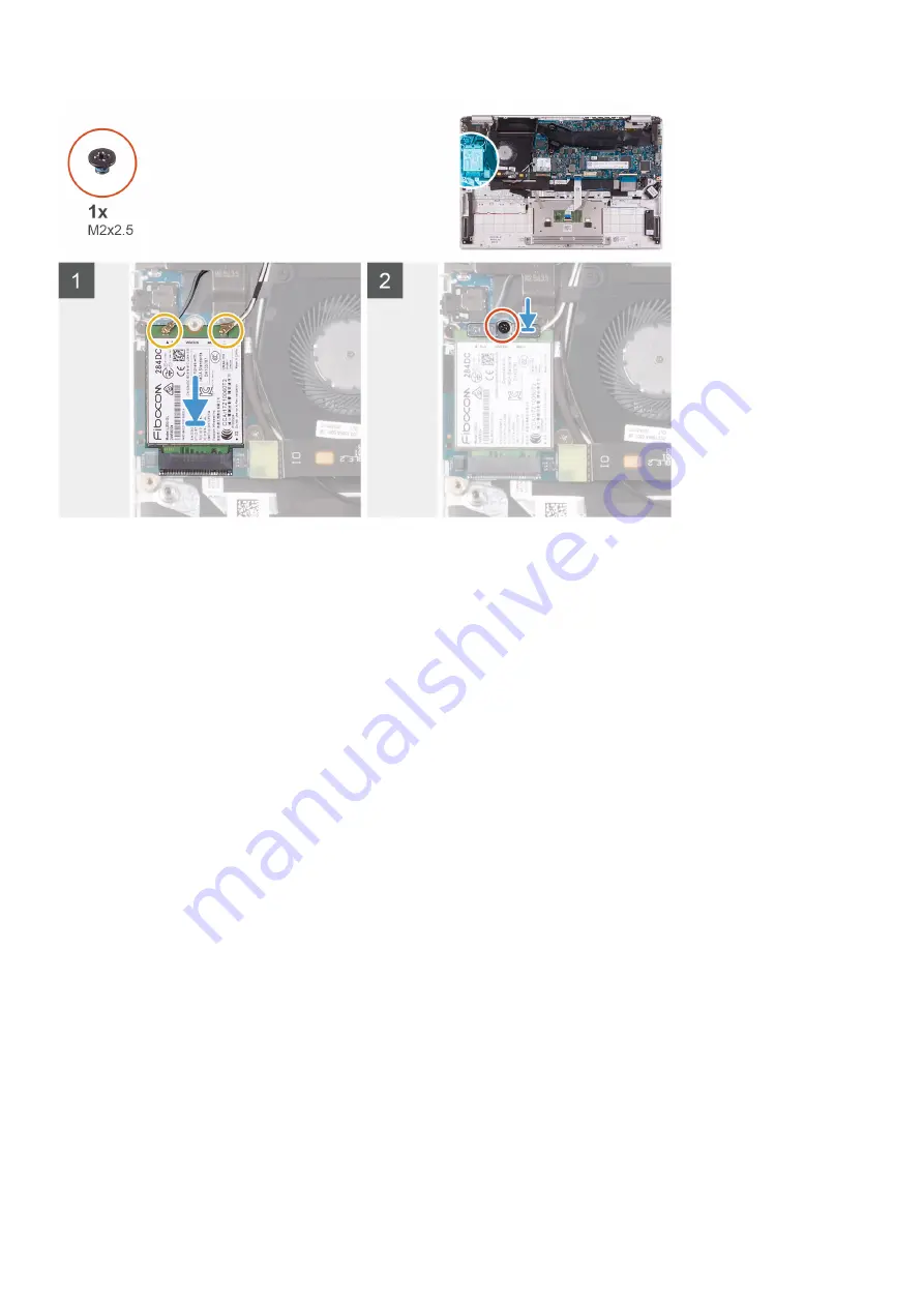
1. Align the notch on the WWAN card with the tab on the WWAN-card slot and insert the WWAN card at an angle into the WWAN-card 

slot.

2. Connect the antenna cables to the WWAN card and align the WWAN-card bracket on the WWAN card.
3. Replace the screw (M2x2.5) that secures the WWAN bracket to the WWAN card.

Next steps

1. Install the 

battery

.

2. Install the 

base cover

.

3. Follow the procedure in 

After working inside your computer

.

Touchpad

Removing the touchpad

Prerequisites

1. Follow the procedure in 

Before working inside your computer

.

2. Remove the 

base cover

.

3. Remove the 

battery

.

About this task

The following image indicates the location of touchpad and provides a visual representation of the removal procedure.

30

Removing and installing components

Summary of Contents for Inspiron 5391

Page 1: ...Inspiron 5391 Service Manual Regulatory Model P114G Regulatory Type P114G001 ...

Page 2: ...age to hardware or loss of data and tells you how to avoid the problem WARNING A WARNING indicates a potential for property damage personal injury or death 2018 2019 Dell Inc or its subsidiaries All rights reserved Dell EMC and other trademarks are trademarks of Dell Inc or its subsidiaries Other trademarks may be trademarks of their respective owners 2019 08 Rev A00 ...

Page 3: ...l battery 14 Installing the coin cell battery 15 Solid state drive 16 Removing the M 2 2280 solid state drive 16 Installing the M 2 2280 solid state drive 17 Removing the M 2 2230 solid state drive 18 Installing the M 2 2230 solid state drive 19 Heat sink 20 Removing the heat sink 20 Installing the heat sink 21 Fan 22 Removing the fan 22 Installing the fan 23 Speakers 25 Removing the speakers 25 I...

Page 4: ...e display bezel 48 Display panel 49 Removing the display panel 49 Installing the display panel 52 Display hinges 55 Removing the display hinges 55 Installing the display hinges 55 Camera 56 Removing the camera 56 Installing the camera 57 Display back cover 58 Removing the display back cover 58 Installing the display back cover 59 Display cable 60 Removing the display cable 60 Installing the displa...

Page 5: ...5 5 Troubleshooting 76 Enhanced Pre Boot System Assessment ePSA diagnostics 76 Running the ePSA diagnostics 76 System diagnostic lights 76 Diagnostics 77 M BIST 78 LCD Built In Self Test BIST 78 Recovering the operating system 78 Flashing BIOS USB key 79 Flashing the BIOS 79 Flea power release 79 Wi Fi power cycle 80 6 Getting help and contacting Dell 81 Contents 5 ...

Page 6: ...pped with the product or at www dell com regulatory_compliance CAUTION Before touching anything inside your computer ground yourself by using a wrist grounding strap or by periodically touching an unpainted metal surface such as the metal at the back of the computer While you work periodically touch an unpainted metal surface to dissipate static electricity which could harm internal components CAU...

Page 7: ...D damage Handle all static sensitive components in a static safe area If possible use anti static floor pads and workbench pads When unpacking a static sensitive component from its shipping carton do not remove the component from the anti static packing material until you are ready to install the component Before unwrapping the anti static packaging ensure that you discharge static electricity fro...

Page 8: ...e returned to Dell it is critical to place these parts in anti static bags for safe transport ESD protection summary It is recommended that all field service technicians use the traditional wired ESD grounding wrist strap and protective anti static mat at all times when servicing Dell products In addition it is critical that technicians keep sensitive parts separate from all insulator parts while ...

Page 9: ...ed to such surface when replacing a component NOTE Screw color may vary with the configuration ordered Table 1 Screw list Component Secured to Screw type Quantity Screw image Base cover Palm rest and keyboard assembly M2x6 4 Battery Palm rest and keyboard assembly M2x2 4 Battery Palm rest and keyboard assembly M1 6x4 1 Touchpad bracket Palm rest and keyboard assembly M1 6x2 3 Touchpad Palm rest an...

Page 10: ...d assembly M2x3 1 Power button with fingerprint reader bracket Palm rest and keyboard assembly M1 6x2 1 Power button with fingerprint reader Palm rest and keyboard assembly M1 6x2 1 Base cover Removing the base cover Prerequisites 1 Follow the procedure in Before working inside your computer About this task The following image indicates the location of the base cover and provides a visual represen...

Page 11: ...m rest and keyboard assembly 4 Lift the base cover off the palm rest and keyboard assembly Installing the base cover Prerequisites If you are replacing a component remove the existing component before performing the installation procedure About this task The following image indicates the location of the base cover and provides a visual representation of the installation procedure Removing and inst...

Page 12: ... the three captive screws that secure the base cover to the palm rest and keyboard assembly Next steps 1 Follow the procedure in After working inside your computer Battery Removing the battery Prerequisites 1 Follow the procedure in Before working inside your computer 2 Remove the base cover About this task The following image indicates the location of the battery and provides a visual representat...

Page 13: ...rd and palm rest and keyboard assembly 4 Lift the battery off the palm rest and keyboard assembly Installing the battery Prerequisites If you are replacing a component remove the existing component before performing the installation procedure About this task The following image indicates the location of the battery and provides a visual representation of the installation procedure Removing and ins...

Page 14: ...er Coin cell battery Removing the coin cell battery Prerequisites 1 Follow the procedure in Before working inside your computer CAUTION Removing the coin cell battery resets the BIOS setup program s settings to default It is recommended that you note the BIOS setup program s settings before removing the coin cell battery 2 Remove the base cover 3 Remove the battery About this task The following im...

Page 15: ... rest and keyboard assembly Installing the coin cell battery Prerequisites If you are replacing a component remove the existing component before performing the installation procedure About this task The following image indicates the location of the coin cell battery and provides a visual representation of the installation procedure Removing and installing components 15 ...

Page 16: ...nstall the base cover 3 Follow the procedure in After working inside your computer Solid state drive Removing the M 2 2280 solid state drive Prerequisites 1 Follow the procedure in Before working inside your computer 2 Remove the base cover 3 Remove the battery About this task The following image indicates the location of the solid state drive and provides a visual representation of the removal pr...

Page 17: ...e system board Installing the M 2 2280 solid state drive Prerequisites If you are replacing a component remove the existing component before performing the installation procedure About this task The following image indicates the location of the solid state drive and provides a visual representation of the installation procedure Removing and installing components 17 ...

Page 18: ...xt steps 1 Install the battery 2 Install the base cover 3 Follow the procedure in After working inside your computer Removing the M 2 2230 solid state drive Prerequisites 1 Follow the procedure in Before working inside your computer 2 Remove the base cover 3 Remove the battery About this task The following image indicates the location of the solid state drive and provides a visual representation o...

Page 19: ...id state drive off the solid state drive slot on the system board Installing the M 2 2230 solid state drive Prerequisites If you are replacing a component remove the existing component before performing the installation procedure About this task The following image indicates the location of the solid state drive and provides a visual representation of the installation procedure Removing and instal...

Page 20: ...res the solid state drive to the system board Next steps 1 Install the battery 2 Install the base cover 3 Follow the procedure in After working inside your computer Heat sink Removing the heat sink Prerequisites 1 Follow the procedure in Before working inside your computer 2 Remove the base cover 3 Remove the battery About this task The following image indicates the location of the heat sink and p...

Page 21: ...he system board 3 Lift the heat sink off the system board Installing the heat sink Prerequisites If you are replacing a component remove the existing component before performing the installation procedure About this task The following image indicates the location of the base cover and provides a visual representation of the installation procedure Removing and installing components 21 ...

Page 22: ...res the heat sink to the system board Next steps 1 Install the battery 2 Install the base cover 3 Follow the procedure in After working inside your computer Fan Removing the fan Prerequisites 1 Follow the procedure in Before working inside your computer 2 Remove the base cover 3 Remove the battery About this task The following image indicates the location of fan and provides a visual representatio...

Page 23: ...palm rest and keyboard assembly 4 Disconnect the fan cable from the system board and completely lift the fan off the palm rest and keyboard assembly Installing the fan Prerequisites If you are replacing a component remove the existing component before performing the installation procedure About this task The following image indicates the location of fan and provides a visual representation of the ...

Page 24: ... screws that secure the fan to the palm rest and keyboard assembly 4 Connect the I O board cable to the system board and I O board NOTE This step is only applicable for computers shipped with a WWAN configuration Next steps 1 Install the battery 2 Install the base cover 3 Follow the procedure in After working inside your computer 24 Removing and installing components ...

Page 25: ... a visual representation of the removal procedure Steps 1 Open the latch and disconnect the touchpad cable from the system board 2 Disconnect the speaker cable from the system board 3 Peel the tapes that secure the speaker cable to the palm rest and keyboard assembly 4 Note the routing of the speaker cable and remove the speaker cable from the routing guides on the palm rest and keyboard assembly ...

Page 26: ...n of speakers and provides a visual representation of the installation procedure Steps 1 Using the alignment posts and rubber grommets place the speakers in the slots on the palm rest and keyboard assembly 2 Route the speaker cable through the routing guides on the palm rest and keyboard assembly 3 Adhere the tapes that secure the speaker cable to the palm rest and keyboard assembly 4 Connect the ...

Page 27: ...tes the location of WLAN card and provides a visual representation of the removal procedure Steps 1 Remove the screw M2x2 5 that secures the WLAN card bracket to the WLAN card and lift the WLAN card bracket off the WLAN card 2 Disconnect the antenna cables from the WLAN card 3 Slide and remove the WLAN card from the WLAN card slot Installing the WLAN card Prerequisites If you are replacing a compo...

Page 28: ... screw M2x2 5 to secure the WLAN card bracket to the WLAN card Next steps 1 Install the battery 2 Install the base cover 3 Follow the procedure in After working inside your computer WWAN card Removing the WWAN card Prerequisites NOTE This procedure is only applicable for computers shipped with a WWAN configuration 1 Follow the procedure in Before working inside your computer 2 Remove the base cove...

Page 29: ...WAN card from the WWAN card slot Installing the WWAN card Prerequisites NOTE This procedure is only applicable for computers shipped with a WWAN configuration If you are replacing a component remove the existing component before performing the installation procedure About this task The following image indicates the location of WWAN card and provides a visual representation of the installation proc...

Page 30: ...he WWAN bracket to the WWAN card Next steps 1 Install the battery 2 Install the base cover 3 Follow the procedure in After working inside your computer Touchpad Removing the touchpad Prerequisites 1 Follow the procedure in Before working inside your computer 2 Remove the base cover 3 Remove the battery About this task The following image indicates the location of touchpad and provides a visual rep...

Page 31: ... keyboard assembly 5 Remove the two M1 6x2 screws that secure the touchpad to the palm rest and keyboard assembly 6 Lift the touchpad along with the cable off the palm rest and keyboard assembly Installing the touchpad Prerequisites If you are replacing a component remove the existing component before performing the installation procedure About this task The following image indicates the location ...

Page 32: ...oard assembly 4 Replace the three M1 6x2 screws that secure the touchpad bracket to the palm rest and keyboard assembly 5 Slide the touchpad cable into its connector on the system board and close the latch to secure the cable 6 Adhere the tape that secures the touchpad to the palm rest and keyboard assembly Next steps 1 Install the battery 2 Install the base cover 3 Follow the procedure in After w...

Page 33: ...e to the system board 3 Open the display hinges at an angle of 90 degrees 4 Disconnect the power adapter port cable from the system board 5 Remove the screw M2x3 that secures the power adapter port to the palm rest and keyboard assembly 6 Lift the power adapter port along with its cable off the palm rest and keyboard assembly Installing the power adapter port Prerequisites If you are replacing a c...

Page 34: ...play hinges 6 Replace the screw M2x4 that secure the right display hinge to the system board Next steps 1 Install the battery 2 Install the base cover 3 Follow the procedure in After working inside your computer Display assembly Removing the display assembly Prerequisites 1 Follow the procedure in Before working inside your computer 2 Remove the base cover 3 Remove the battery About this task The ...

Page 35: ...Removing and installing components 35 ...

Page 36: ...y cable from the system board 4 Remove the two screws M2 5x3 5 that secure the left display hinge to the I O board and palm rest and keyboard assembly 5 Remove the screw M2x4 that secures the right display hinge to the system board 6 Open the display hinges at an angle of 90 degrees 7 Remove the palm rest and keyboard assembly off the display assembly 36 Removing and installing components ...

Page 37: ... component remove the existing component before performing the installation procedure About this task The following image indicates the location of display assembly and provides a visual representation of the installation procedure Removing and installing components 37 ...

Page 38: ...ly 4 Replace the screw M2x4 that secures the right display hinge to the system board 5 Connect the display cable on to the connector on the system board 6 Align and place the display cable bracket on the display cable 7 Replace the screw M2x4 that secures the display cable bracket to the system board Next steps 1 Install the battery 2 Install the base cover 3 Follow the procedure in After working ...

Page 39: ...llowing image indicates the location of I O board and provides a visual representation of the removal procedure Steps 1 Remove the two screws M2 5x3 5 that secure the left display hinge to the I O board and palm rest and keyboard assembly 2 Open the display hinges at an angle of 90 degrees 3 Peel the tape that secures the I O board cable to the I O board Removing and installing components 39 ...

Page 40: ... the existing component before performing the installation procedure About this task The following image indicates the location of I O board and provides a visual representation of the installation procedure Steps 1 Align and place the I O board on the palm rest and keyboard assembly 2 Replace the screw M2x3 that secures the I O board to the palm rest and keyboard assembly 3 Replace the screw M2 5...

Page 41: ...isites 1 Follow the procedure in Before working inside your computer 2 Remove the base cover 3 Remove the battery 4 Remove the WLAN card 5 Remove the fan 6 Remove the I O board About this task The following image indicates the location of power button and provides a visual representation of the removal procedure Steps 1 Remove the screw M1 6x2 that secures the power button bracket to the palm rest...

Page 42: ...ton board to the palm rest and keyboard assembly 3 Align the screw hole on the power button bracket with the screw hole on the palm rest and keyboard assembly 4 Replace the screw M1 6x2 that secures the power button bracket to the palm rest and keyboard assembly Next steps 1 Install the I O board 2 Install the fan 3 Install the WLAN card 4 Install the battery 5 Install the base cover 6 Follow the ...

Page 43: ...disconnect the fingerprint reader cable from the fingerprint reader board 4 Lift the power button with fingerprint reader along with the power button cable off the palm rest and keyboard assembly 5 Lift the power button with fingerprint reader along with the power button cable off the palm rest and keyboard assembly Installing the power button with fingerprint reader Prerequisites NOTE This proced...

Page 44: ...he screw M1 6x2 that secure the power button bracket to the palm rest and keyboard assembly Next steps 1 Install the I O board 2 Install the fan 3 Install the WLAN card 4 Install the battery 5 Install the base cover 6 Follow the procedure in After working inside your computer System board Removing the system board Prerequisites 1 Follow the procedure in Before working inside your computer 2 Remove...

Page 45: ...ect the speaker cable from the system board 7 Open the latch and disconnect the fingerprint reader cable from the system board 8 Open the latch and disconnect the touchpad cable from the system board 9 Open the latch and disconnect the keyboard cable from the system board 10 Open the latch and disconnect the keyboard backlit cable from the system board 11 Disconnect the coin cell battery cable fro...

Page 46: ...the screw holes on the palm rest and keyboard assembly 2 Replace the screw M2x4 that secures the system board to palm rest and keyboard assembly 3 Connect the display cable on to the connector on the system board6 4 Connect the power adapter port cable to the system board 5 Connect the coin cell battery cable to the system board 6 Connect the keyboard backlit cable to the system board and close th...

Page 47: ...tall the power adapter port 2 Install the display assembly 3 Install the heat sink 4 Install the fan 5 Install the WLAN card 6 Install the M 2 2280 solid state drive or M 2 2230 solid state drive whichever applicable 7 Install the battery 8 Install the base cover 9 Follow the procedure in After working inside your computer Display bezel Removing the display bezel Prerequisites NOTE This procedure ...

Page 48: ...lay bezel Prerequisites NOTE This procedure is not applicable to computers shipped with a WWAN configuration If you are replacing a component remove the existing component before performing the installation procedure About this task The following image indicates the location of display bezel and provides a visual representation of the installation procedure 48 Removing and installing components ...

Page 49: ...isplay panel Removing the display panel Prerequisites NOTE This procedure is not applicable to computers shipped with a WWAN configuration 1 Follow the procedure in Before working inside your computer 2 Remove the base cover 3 Remove the battery 4 Remove the WLAN card 5 Remove the display assembly 6 Remove the display bezel About this task The following image indicates the location of display pane...

Page 50: ...50 Removing and installing components ...

Page 51: ...Removing and installing components 51 ...

Page 52: ...cover 5 Peel the tape that secures the display cable to the display back cover 6 Open the latch and disconnect the display cable from the display back cover Installing the display panel Prerequisites NOTE This procedure is not applicable to computers shipped with a WWAN configuration If you are replacing a component remove the existing component before performing the installation procedure About t...

Page 53: ...Removing and installing components 53 ...

Page 54: ...Adhere the pressure film on the display panel 7 Using the flat end of the plastic scribe or handle of the screwdriver press and roll over the pressure films until they turn pink 8 Peel off the pressure film from the display panel 9 Place the display bezel on the display back cover and snap it into place Next steps 1 Install the display bezel 2 Install the display assembly 3 Install the WLAN card 4...

Page 55: ...of display hinges and provides a visual representation of the removal procedure Steps 1 Remove the four M2 5x2 5 screws that secure the display hinges to the display back cover 2 Remove the two M2x2 screws that secure the display hinges to the display back cover 3 Lift the display hinges off the display back cover Installing the display hinges Prerequisites NOTE This procedure is not applicable to...

Page 56: ...splay back cover Next steps 1 Install the display bezel 2 Install the display assembly 3 Install the WLAN card 4 Install the battery 5 Install the base cover 6 Follow the procedure in After working inside your computer Camera Removing the camera Prerequisites NOTE This procedure is not applicable to computers shipped with a WWAN configuration 1 Follow the procedure in Before working inside your co...

Page 57: ...isconnect the camera cable off the camera 4 Peel the tape off the camera and lift the camera off the display back cover Installing the camera Prerequisites NOTE This procedure is not applicable to computers shipped with a WWAN configuration If you are replacing a component remove the existing component before performing the installation procedure About this task The following image indicates the l...

Page 58: ...he WLAN card 5 Install the battery 6 Install the base cover 7 Follow the procedure in After working inside your computer Display back cover Removing the display back cover Prerequisites NOTE This procedure is not applicable to computers shipped with a WWAN configuration 1 Follow the procedure in Before working inside your computer 2 Remove the base cover 3 Remove the battery 4 Remove the WLAN card...

Page 59: ... and keyboard assembly for computers shipping with WLAN configurations Installing the display back cover Prerequisites NOTE This procedure is not applicable to computers shipped with a WWAN configuration If you are replacing a component remove the existing component before performing the installation procedure About this task The following image indicates the display back cover and provides a visu...

Page 60: ... 9 Install the base cover 10 Follow the procedure in After working inside your computer Display cable Removing the display cable Prerequisites NOTE This procedure is not applicable to computers shipped with a WWAN configuration 1 Follow the procedure in Before working inside your computer 2 Remove the base cover 3 Remove the battery 4 Remove the display assembly 5 Remove the display panel 6 Remove...

Page 61: ...E This procedure is not applicable to computers shipped with a WWAN configuration If you are replacing a component remove the existing component before performing the installation procedure About this task The following image indicates the location of display cable and provides a visual representation of the installation procedure Removing and installing components 61 ...

Page 62: ...g inside your computer Palm rest and keyboard assembly Removing the palm rest and keyboard assembly Prerequisites 1 Follow the procedure in Before working inside your computer 2 Remove the base cover 3 Remove the battery 4 Remove the WLAN card 5 Remove the speakers 6 Remove the system board 7 Remove the display assembly 8 Remove the power button with fingerprint reader or power button board whiche...

Page 63: ...of the display back cover for computers shipping with WWAN configuration NOTE System board can be removed with heatsink attached Installing the palm rest and keyboard assembly Prerequisites If you are replacing a component remove the existing component before performing the installation procedure About this task The following image indicates the palm rest and keyboard assembly and provides a visua...

Page 64: ... the touchpad 2 Install the power adapter port 3 Install the power button with fingerprint reader or power button board whichever applicable 4 Install the display assembly 5 Install the system board 6 Install the speakers 7 Install the WLAN card 8 Install the battery 9 Install the base cover 10 Follow the procedure in After working inside your computer 64 Removing and installing components ...

Page 65: ...l com support Intel Trusted Execution Engine Interface In the Device Manager check if the Intel Trusted Execution Engine Interface driver is installed Install the driver update from www dell com support Intel Virtual Button driver In the Device Manager check if the Intel Virtual Button driver is installed Install the driver updates from www dell com support Wireless and Bluetooth drivers In the De...

Page 66: ... a user selectable option such as the user password type of hard drive installed and enabling or disabling base devices Entering BIOS setup program Steps 1 Turn on or restart your computer 2 During POST when the DELL logo is displayed watch for the F2 prompt to appear and then press F2 immediately NOTE The F2 prompt indicates that the keyboard is initialized This prompt can appear very quickly so ...

Page 67: ...e boot sequence screen also displays the option to access the System Setup screen System setup options NOTE Depending on this computer and its installed devices the items that are listed in this section may or may not be displayed Table 2 System setup options System information menu Overview BIOS Version Displays the BIOS version number Service Tag Displays the Service Tag of the computer Asset Ta...

Page 68: ...lays the technology that is used for the memory Device Information Video Controller Displays the integrate graphics information of the computer dGPU Video Controller Displays the discrete graphics information of the computer Video BIOS Version Displays the video BIOS version of the computer Video Memory Displays the video memory information of the computer Panel Type Displays the Panel Type of the...

Page 69: ...Configuration Enable Boot Support Enables or disables booting from USB mass storage devices such as external hard drive optical drive and USB drive Enable External USB Ports Enables or disables USB ports to be functional in an operating system environment SATA Operation Configures operating mode of the integrated SATA hard drive controller Default RAID SATA is configured to support RAID Intel Rapi...

Page 70: ...dmin Password is set Default OFF Password Bypass Bypass the System Boot Password and the internal hard drive password prompts during a system restart Default Disabled Enable Non Admin Password Changes Enables or disables the user to change the system and hard drive password without the need for admin password Default ON Non Admin Setup Changes Allow Wireless Switch Changes Enables or disables chan...

Page 71: ...isables the master password support Default OFF Table 7 System setup options Secure Boot menu Secure Boot Enable Secure Boot Enables or disables the computer to boos using only validated boot software Default OFF NOTE For Secure Boot to be enabled the computer needs to be in UEFI boot mode and the Enable Legacy Option ROMs option needs to be turned off Secure Boot Mode Selects the Secure Boot oper...

Page 72: ...e Configuration Enables the computer to run on battery during power usage hours Use the below options to prevent AC power usage between certain times of each day Default Adaptive Battery settings are adaptively optimized based on your typical battery usage pattern Enable Advanced Battery Charge Configuration Enables Advanced Battery Charge Configuration from the beginning of the day to a specified...

Page 73: ...ST Time Configures the BIOS POST Power On Self Test load time Default 0 seconds Fastboot Configures the speed of the UEFI boot process Default Thorough Performs complete hardware and configuration initialization during boot Fn Lock Options Enables or disables the Fn lock mode Default ON Lock Mode Default Lock Mode Secondary Lock Mode Secondary If this option is selected the F1 F12 keys scan the co...

Page 74: ...puter to automatically recover the BIOS without user actions This feature requires BIOS Recovery from Hard Drive to be set to Enabled Default OFF Start Data Wipe CAUTION This Secure Wipe Operation will delete information in a way that it cannot be reconstructed If enabled the BIOS will queue up a data wipe cycle for storage devices that are connected to the motherboard on the next reboot Default O...

Page 75: ...one minute 5 Replace the coin cell battery 6 Connect the battery cable to the system board 7 Replace the base cover Clearing BIOS System Setup and System passwords About this task To clear the system or BIOS passwords contact Dell technical support as described at www dell com contactdell NOTE For information on how to reset Windows or application passwords refer to the documentation accompanying ...

Page 76: ...r 2 As the computer boots press the F12 key as the Dell logo appears 3 On the boot menu screen select the Diagnostics option 4 Click the arrow at the bottom left corner Diagnostics front page is displayed 5 Click the arrow in the lower right corner to go to the page listing The items detected are listed 6 To run a diagnostic test on a specific device press Esc and click Yes to stop the diagnostic ...

Page 77: ...r Camera status light Indicates whether the camera is in use Solid white Camera is in use Off Camera is not in use Caps Lock status light Indicates whether Caps Lock is enabled or disabled Solid white Caps Lock enabled Off Caps Lock disabled Diagnostics Table 18 Diagnostics M BIST Built In Self Test L BIST LCD Built In Self Test Purpose of diagnostic tool Evaluates the health of the system board a...

Page 78: ...BIST test Steps 1 Power off your computer 2 Disconnect any peripherals connected to your computer Connect only the supplied AC power adapter to your computer 3 Ensure that the LCD screen is clean with no dust particles on the surface of the screen 4 From the power off state press and hold the D key and power button to enter LCD BIST mode Continue to hold the D key until you see color bars on the L...

Page 79: ... to flash update the BIOS when an update is available or when you replace the system board Follow these steps to flash the BIOS Steps 1 Turn on your computer 2 Go to www dell com support 3 Click Product support enter the Service Tag of your computer and then click Submit NOTE If you do not have the Service Tag use the auto detect feature or manually browse for your computer model 4 Click Drivers d...

Page 80: ...be performed The following procedure provides the instructions on how to conduct a Wi Fi power cycle NOTE Some ISPs Internet Service Providers provide a modem router combo device Steps 1 Turn off your computer 2 Turn off the modem 3 Turn off the wireless router 4 Wait for 30 seconds 5 Turn on the wireless router 6 Turn on the modem 7 Turn on your computer 80 Troubleshooting ...

Page 81: ... the related articles Learn and know the following information about your product Product specifications Operating system Setting up and using your product Data backup Troubleshooting and diagnostics Factory and system restore BIOS information See Me and My Dell at www dell com support manuals To locate the Me and My Dell relevant to your product identify your product through one of the following ...

Reviews: