background image

Back to Contents Page


Ports and Connectors: 

Dell™ Inspiron™ 3700 System Reference


About the I/O Connectors


You can connect external devices to the input/output (I/O) connectors. The computer's basic input/output system (BIOS) detects the presence of 
external devices when you boot (start) or reboot your computer. 

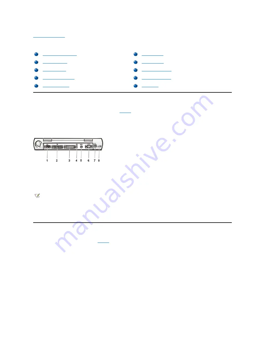
Figure 1

 shows the connectors on the back of your computer.


Figure 1. I/O Connectors


Audio Connectors


You can connect audio devices such as speakers, microphones, headphones, and record/playback devices to your computer. The following 
information tells you how to connect the cables. 

Figure 2

 shows the locations of the audio connectors and the TV-out S-video connector. 


l

Connect the audio cable from a microphone to the microphone-in connector.  
 

l

Connect the audio cable from the speakers to the line-out connector.  
 

l

Connect the line-out cable from a record/playback device to the line-in connector. Cassette players, CD players, radios, stereo systems, and 
tape players are all record/playback devices. 
 

l

Connect the TV-out S-video I/O cable from a record/playback device to the TV-out S-video connector. VCRs and video cameras are 
record/playback devices.


Figure 2. Connecting Audio and S-Video Devices


About the I/O Connectors 

USB Connector

Audio Connectors


PS/2 Connector

Video Connector

Serial Port Connector

Parallel Port Connector

AC Power Connector


Docking Connector

Infrared Port

NOTICE: When disconnecting external devices from the back of the computer, wait 5 seconds after turning off the 
computer before you disconnect a device to avoid possible damage to the system board.

1

Video connector

5

Mini-Deutsche Industrie Norm (DIN) PS/2 connector

2

 Parallel port connector

6

Serial port connector

3

Docking connector

7

AC power connector

4

USB connector 

8

Infrared port

NOTES: Some external devices require you to load software called device drivers into system memory before the 
devices will work. These device drivers help your computer recognize the external device and direct its operation. 
Instructions for installing this software are usually included in the upgrade kits. 
 
The advanced port replicator (APR) has the same I/O connectors as your computer. In addition, the APR has a second 
Personal System/2 (PS/2) connector, a second Universal Serial Bus (USB) connector, and an Ethernet network 
connector.

Summary of Contents for Inspiron 3700

Page 1: ...k of Intel Corporation Adobe is a trademark of Adobe Systems Incorporated which may be registered in certain jurisdictions Other trademarks and trade names may be used in this document to refer to either the entities claiming the marks and names or their products Dell Computer Corporation disclaims any proprietary interest in trademarks and trade names other than its own Initial release 20 Sep 199...

Page 2: ...ter perform the following steps 1 Connect the AC adapter power cable to the AC adapter See Figure 1 2 Plug the AC adapter power cable into an electrical outlet 3 Plug the AC adapter cable into the AC adapter connector on the computer Figure 1 Connecting the AC Adapter Turning the Computer On To turn on the computer press the power button See Figure 1 in Introduction Back to Contents Page NOTE If y...

Page 3: ...ed with the Power Management Properties window in the Control Panel Closing the Display One way to conserve power on the computer is to close the display when the computer is not in use When you close the display and an external NOTE For Advanced Configuration and Power Interface ACPI compliant systems power management settings are controlled from the Power Management Properties window in the Cont...

Page 4: ...ea the S2D partition on the hard disk drive and then turns off all power to the computer When you resume normal operation the same programs will be running and the same files will be open that were loaded before you activated this mode Place the computer in S2D mode if you intend to store the computer for longer than 40 days S2D mode preserves the configuration information stored in nonvolatile ra...

Page 5: ...hen the computer resumes from standby mode l Hibernate ACPI only Allows you to enable the hibernate feature Power Management Properties for Microsoft Windows NT Dell provides Softex software compatible with the Power Management Controller which allows you to suspend and resume your portable computer without affecting your ability to use the docking station or its media bay For information about So...

Page 6: ... the computer draws power first from the battery in the media bay The AC adapter first charges the battery in the battery bay l The integrated charge gauge lets you check a battery s charge before you insert it into the computer l The battery s self test capability alerts you to battery conditions such as low charge l There is no battery memory effect with lithium ion batteries you can charge the ...

Page 7: ...essing Fn Esc or Scroll Lock Esc on an external keyboard if the External Hot Key option is enabled in the System Setup program l Use the save to disk suspend S2D mode Place the computer in S2D mode by pressing Fn a or Fn q on a French keyboard When the green power indicator turns off continue If you have your AC adapter connected to your computer go to step 5 5 Remove the battery from the battery ...

Page 8: ... or Fn q on a French keyboard When the green power indicator turns off continue to step 6 6 Remove any device that may be installed in the media bay see Figure 2 a Close the computer display and turn the computer over b Slide the media bay latch toward the Unlock icon to release the device in the bay Hold the latch in the unlock position while pulling the device out of the bay c Release the latch ...

Page 9: ... and the computer is not connected to an electrical outlet Figure 4 shows the battery indicator status lights Figure 4 Status Lights After the first low battery warning if no input output I O activity occurs within 75 seconds the computer activates S2D mode If the computer has no S2D partition the computer enters standby mode The computer can preserve data for several hours in standby mode If you ...

Page 10: ...ead to unpredictable operation To obtain a new battery call Dell or access the Dell World Wide Web site at http www dell com Dell suggests you follow these precautions when using the battery l To avoid installing a defective battery in your computer first check the battery s charge indicated by the battery charge indicators on the battery itself by pressing the battery test button See Figure 2 l I...

Page 11: ... CAUTION Do not puncture or incinerate the battery NOTES This computer is supplied with a lithium ion battery which is significantly less hazardous to the environment than the lithium metal technology used in some other batteries such as watch batteries Lithium ion batteries are longer lived than conventional batteries and do not require replacement as often Spent batteries should not be placed in...

Page 12: ...e DVD into the tray label side up Make sure that the DVD is seated correctly on the spindle by pressing down on the disc until it clicks in place Then gently push in the tray When the CD ROM or DVD ROM drive is in use the drive access indicator blinks on the computer s front panel Caring for CDs and DVDs When handling and using CDs and DVDs follow these precautions l Never use a damaged or warped ...

Page 13: ...ve Differential Pulse Code modulation ADPCM l CD I mode 2 form 1 and form 2 l CD I Ready l CD Bridge l Photo CD CD recordable CD R single and multisession l Video CD l CD rewritable CD RW the 24x CD ROM and DVD ROM drives support reading CD RW discs this format is supported as read only neither the CD ROM nor the DVD ROM drive can write to this type of disc l DVD 5 the DVD ROM drive supports the D...

Page 14: ...t the computer for the device to be recognized To install a device in the media bay perform the following steps 1 Verify that the Diskette Reconfig option in the System Setup program is set to Any Time 2 Save your work and close all open files and application programs 3 If the computer is docked undock it 4 Double click the Docking Services or BayManager icon in the Windows system tray on the task...

Page 15: ...ve For detailed instructions on installing devices in the media bay see Using the Media Bay in Chapter 2 of the Reference and Troubleshooting Guide The diskette drive lets you install programs and transfer data using 3 5 inch diskettes Figure 1 Diskette Drive Installed in Computer To use the diskette drive insert a 3 5 inch diskette into the drive label side up and metal end first Push the diskett...

Page 16: ...place the DVD into the tray label side up Make sure that the DVD is seated correctly on the spindle by pressing down on the disc until it clicks in place Then gently push in the tray When the CD ROM or DVD ROM drive is in use the drive access indicator blinks on the computer s front panel Caring for CDs and DVDs When handling and using CDs and DVDs follow these precautions l Never use a damaged or...

Page 17: ...rease the volume Press Fn End to enable or disable both the integrated and external speakers See Utilities and Drivers for Microsoft Windows 98 and Utilities and Drivers for Microsoft Windows NT for information about reinstalling the audio drivers The drivers are located on the System Software CD Embedded Numeric Keypad As you work you may want to use the embedded numeric keypad see Figure 3 to en...

Page 18: ...as no effect on an active matrix display Fn F5 Toggles the computer s display between regular video mode and reverse video mode white on black This key combination works only if the computer is in text mode it has no effect if the computer is running a graphical operating system or application program Fn F7 Toggles the computer s display between expanded mode and regular video mode Fn F8 Switches ...

Page 19: ...led in the System Setup program Key Combinations Function Fn Switches between the microprocessor s maximum speed and a slower compatibility speed Ctrl In full MS DOS mode or in a full screen DOS box switches between the microprocessor s maximum speed and a slower compatibility speed NOTE When using the integrated keyboard you press Fn and the appropriate keys to perform certain functions see Table...

Page 20: ...e touch pad use the following techniques l To move the cursor lightly slide your finger over the smooth sensor area l To select an object gently tap once on the surface of the touch pad or use your thumb to press the left touch pad button The touch pad buttons perform standard mouse functions l To select and move or drag an object position the cursor on the object and double tap on the touch pad O...

Page 21: ...d Pointing Device The DualPoint integrated pointing device software allows you to set the default for the type of cursor pointing device you want to use as well as sensitivity motion and drag and drop features of both the touch pad and track stick To customize the DualPoint integrated pointing device perform the following steps 1 Click the Start button point to Settings and click Control Panel 2 D...

Page 22: ...PC Card see Figure 7 perform the following steps 1 If necessary remove the blank from the PC Card connector you intend to use by pressing the eject button and pulling the blank out 2 Hold the card with its orientation symbol pointing into the slot and the top side of the card facing up 3 Insert the card into the slot and press in firmly until the card is completely seated in the internal PC Card c...

Page 23: ...ion see the operating system documentation Display Adjusting the Brightness To accommodate local lighting conditions or video output from the software you are using you can use the key combinations shown in Table 7 Table 7 Brightness Key Combinations and Their Functions operation of the card before you remove it If you do not remove the card in the configuration utility you could lose data from op...

Page 24: ...mage to the display Extended Desktop Mode With the Microsoft Windows 98 operating system you can use an external monitor as an extension of your display The extended desktop feature gives your computer the ability to display video of different content and resolution on both the computer display screen and the external display To set up your computer for extended desktop perform the following steps...

Page 25: ...splay video of the same content and resolution on both the computer display screen and the external monitor is not supported if the computer is booted to MS DOS using a full screen MS DOS session under a Microsoft Windows operating system or the ATI Mobility M1 video driver is not loaded This limitation may also be noted in operating systems other than Microsoft Windows ...

Page 26: ...wn country use area codes instead of international access codes country codes and city codes For example to call Paris France from Montpellier France dial the area code plus the local number as shown in the following illustration The codes required depend on where you are calling from as well as the destination of your call in addition each country has a different dialing protocol If you need assi...

Page 27: ...al support toll free 1 800 247 9362 Customer Care From outside Toronto toll free 1 800 387 5759 Customer Care From within Toronto 416 758 2400 Customer Technical Support toll free 1 800 847 4096 Sales Direct Sales from outside Toronto toll free 1 800 387 5752 Sales Direct Sales from within Toronto 416 758 2200 Sales Federal government education and medical toll free 1 800 567 7542 Sales Major Acco...

Page 28: ...ll free 1 800 822 8965 Public Americas International systems purchased by governmental agencies local state or federal or educational institutions Customer Service and Technical Support Return Material Authorization Numbers toll free 1 800 234 1490 Dell Sales toll free 1 800 289 3355 toll free 1 800 879 3355 Spare Parts Sales toll free 1 800 357 3355 DellWare toll free 1 800 753 7201 DellWare FaxB...

Page 29: ...asby Sweden 859005594 Fax Switchboard 45170117 Web site http support euro dell com dk E mail den_support dell com Finland Helsinki Technical Support 09 253 313 60 Technical Support Fax 09 253 313 81 Customer Care 09 253 313 61 Fax 09 253 313 99 Switchboard 09 253 313 00 Web site http support euro dell com fi E mail fin_support dell com France Paris Montpellier Technical Support 0803 387 270 Custom...

Page 30: ...mbourg call Belgium for sales customer and technical assistance Technical Support Brussels Belgium 02 481 92 88 Home Small Business Sales Brussels Belgium toll free 080016884 Corporate Sales Brussels Belgium 02 481 91 00 Customer Care Brussels Belgium 02 481 91 19 Switchboard Brussels Belgium 02 481 91 00 Fax Brussels Belgium 02 481 92 99 Web site http support euro dell com be E mail tech_be dell ...

Page 31: ...r Care 08 590 05 169 Fax Technical Support 08 590 05 594 Sales 08 590 05 185 Web site http support euro dell com se E mail swe_support dell com Switzerland Geneva Technical Support 0844 811 411 Customer Care 0848 802 802 Switchboard 022 799 01 01 Fax 022 799 01 90 Web site http support euro dell com ch E mail swisstech dell com U K Bracknell Technical Support 0870 908 0800 Corporate Customer Care ...

Page 32: ...port WorkStation OptiPlex and Latitude toll free 0120 1984 39 Y2K Support 044 556 4298 Customer Care 044 556 4240 Direct Sales 044 556 3344 Commercial Sales 044 556 3430 556 3440 Faxbox Service 03 5972 5840 Switchboard 044 556 4300 Korea Seoul NOTE Customers in Korea call Malaysia for customer assistance Technical Support toll free 080 200 3800 Transaction Sales toll free 080 200 3600 Corporate Sa...

Page 33: ...utheast Asian Pacific Countries excluding Australia Brunei China Hong Kong Japan Korea Macau Malaysia New Zealand Singapore Taiwan and Thailand refer to individual listings for these countries Customer Technical Support Customer Service and Sales Penang Malaysia 60 4 810 4810 Taiwan NOTE Customers in Taiwan call Malaysia for customer assistance Technical Support toll free 0080 651 226 0800 33 557 ...

Page 34: ... a single function Example Ctrl Alt Enter l Commands presented in lowercase bold are for reference purposes only and are not intended to be typed when referenced Example Use the format command to In contrast commands presented in the Courier New font are part of an instruction and intended to be typed Example Type format a to format the diskette in drive A l Filenames and directory names are prese...

Page 35: ...to Contents Page Customizing Your Computer Dell Inspiron 3700 System Reference Back to Contents Page Using the System Setup Program System Setup Options Power Management Settings Save to Disk Suspend Utility ...

Page 36: ... limit is reached l A menu category called Devices that briefly describes each test and its parameters l A menu category called Config that describes the configuration of the devices in the selected device group l Status messages that inform you whether test groups or subtests were completed successfully l Error messages that appear if any problems are detected When to Use the Dell Diagnostics Whe...

Page 37: ...evices to Test from the Diagnostics Menu the main screen of the diagnostics appears see Figure 2 The main screen lists the diagnostic test device groups lists the devices of the selected device group and allows you to select categories from a menu From this screen you can enter two other types of screens Information on the main screen of the diagnostics is presented in the following five areas l T...

Page 38: ...which is an address that tells the computer where to send outgoing information and where to look for incoming information Because your printer is a parallel communications device the computer recognizes the printer by its LPT1 address and identifies it as a parallel port You can test your printer connection in the Parallel Ports tests How to Use Dell Diagnostics Six comprehensive menu driven onlin...

Page 39: ... hard shells Diskette recording capacities are small and access times are slow relative to hard disk drives but they provide a convenient means of storing and transferring data Test Category The Test Help category provides a thorough explanation of the test procedure of each presently highlighted test group subtest An example of the Diskette subtest Diskette Drive Seek Test is as follows Diskette ...

Page 40: ...skette out of the drive When data is being accessed from the diskette drive in the media bay the drive access indicator blinks Back to Contents Page NOTE If the computer is docked to the Inspiron 3700 Advanced Port Replicator APR turn off the computer and undock it before installing or removing a diskette drive NOTICE Do not travel with a diskette in the diskette drive Doing so could break the eje...

Page 41: ...er s brightness control to the lowest setting that affords comfortable viewing You can conserve up to 10 percent of battery power by using the minimum brightness setting Key Combinations Function Fn down arrow Decreases brightness Fn up arrow Increases brightness Fn right arrow Decreases contrast has no effect on an active matrix display Fn left arrow Increases contrast has no effect on an active ...

Page 42: ...5 85 Hz 60 Hz NTSC 50 Hz PAL 1024 x 768 XGA 65 k 16 bit 60 70 75 85 Hz 60 Hz NTSC 50 Hz PAL 1024 x 768 XGA 16 M 24 bit 60 70 75 85 Hz 60 Hz NTSC 50 Hz PAL 1024 x 768 XGA 4 2 B 32 bit 60 70 75 85 Hz 60 Hz NTSC 50 Hz PAL 1280 x 1024 SXGA 256 8 bit 60 70 75 85 Hz 60 Hz NTSC 50 Hz PAL 1280 x 1024 SXGA 65 k 16 bit 60 70 75 85 Hz 60 Hz NTSC 50 Hz PAL 1280 x 1024 SXGA 16 M 24 bit 60 70 75 85 Hz 60 Hz NTS...

Page 43: ...g steps 1 Connect the external monitor TV or projector 2 Click the Start button point to Settings and then click Control Panel 3 In the Control Panel window double click the Display icon 4 In the Display Properties window click the Settings tab 5 Change the Colors option to 256 Color or True Color 24 bit 6 Change the Screen Area to the appropriate size for your display 7 Click the Advanced button ...

Page 44: ...ed out In this case press any key on the keyboard to resume normal operation 2 If the low battery light is blinking connect the AC adapter to the computer or replace the battery 3 Adjust the brightness 4 If your computer is attached to an external monitor press Fn F8 to switch the video image to the display Back to Contents Page NOTE True Simul mode the ability to simultaneously display video of t...

Page 45: ...ype regsvr32 popup ocx and then press Enter 5 Click OK when the installation is complete 6 Right click the following link to the Help file Dell Inspiron 3700 System Help chm 3165 KB 7 Click Save Target As in Microsoft Internet Explorer or Save Link As in Netscape Navigator and specify a location on your hard disk drive Viewing the Help File To view the Help file perform the following steps 1 Click...

Page 46: ...crosoft Windows 98 Operating System Drivers Installing the Microsoft Windows NT Operating System Drivers Back to Contents Page NOTE For more information on using the operating system installed on your computer by Dell see the operating system user s guide that came with your computer ...

Page 47: ...reasing available memory One or more memory modules may be faulty or improperly seated Reseat the memory modules and if necessary replace them Disk C failed initialization The hard disk drive failed initialization Run the Hard Disk Drive tests in the Dell Diagnostics Diskette drive 0 seek failure A cable may be loose or the system configuration information may not match the hardware configuration ...

Page 48: ...oid touching the keyboard or the mouse during the boot routine If the problem persists run the Keyboard Controller test in the Dell Diagnostics Keyboard data line failure A cable or connector may be loose or the keyboard may be faulty Run the Keyboard Controller test in the Dell Diagnostics Keyboard stuck key failure If an external keyboard or keypad is being used a cable or connector may be loose...

Page 49: ...sk drive Run the appropriate utility to check the file structure on the diskette or hard disk drive If a large number of sectors are defective back up the data if possible and then reformat the diskette or hard disk drive Seek error The operating system cannot find a specific track on the diskette or hard disk drive If the error is on the diskette drive try another diskette in the drive Shutdown f...

Page 50: ...ll Diagnostics If the program does not load call Dell for technical assistance 3 1 2 Master DMA register failure Run the System Set tests in the Dell Diagnostics If the program does not load call Dell for technical assistance 3 1 3 Master interrupt mask register failure Call Dell for technical assistance 3 1 4 Slave interrupt mask register failure Call Dell for technical assistance 3 2 4 Keyboard ...

Page 51: ...able for use by a PC Card or audio controller if the parallel port is disabled IRQ8 Reserved generated by the system I O controller s real time clock RTC IRQ9 Reserved generated by the video controller IRQ10 Available for use by a PC Card or audio controller unless the Inspiron 3700 Advanced Port Replicator APR is attached IRQ11 Generated by Universal Serial Bus USB PC Card and audio controllers a...

Page 52: ...20 003F Interrupt controller 1 0040 005F System timers 0060 006F Keyboard controller 0070 007F RTC and nonmaskable interrupt NMI enable 0080 009F DMA page registers 00A0 00BF Interrupt controller 2 00C0 00DF DMA controller 2 00F0 00FF Math coprocessor 0170 0177 CD ROM drive controller 01F0 01F7 Hard disk drive controller 0210 0217 Audio controller 0220 022F Audio controller 0270 0277 Fast IR 0376 ...

Page 53: ...the line out speaker out jack l Connect the line out cable from a record playback device to the line in audio in jack Cassette players CD players radios stereo systems and tape players are all record playback devices l Connect the S Video input output I O cable from a record playback device to the S Video connector VCRs and video cameras are record playback devices Figure 2 Connecting Audio and S ...

Page 54: ...able to your television s composite video connector Keyboard You can attach a Personal System 2 PS 2 compatible external 101 or 102 key keyboard to the computer s mini Deutsche Industrie Norm DIN connector as shown in Figure 3 Figure 3 Attaching an External Keyboard You can use the computer s keyboard and an external keyboard at the same time When you attach a keyboard to the computer the embedded...

Page 55: ...5 Connecting an External Monitor Be sure to tighten all the screws on the video cable connector s to eliminate radio frequency interference RFI 3 Connect your external monitor to a grounded electrical outlet Plug the three prong connector on one end of the monitor s power cable into a grounded power strip or some other grounded power source If the cable is not permanently attached to the monitor c...

Page 56: ...ou will not see an image on either the computer s display or the external monitor To see an image turn on the external monitor or switch the video image to the computer s display by pressing Fn F8 on the keyboard or Scroll Lock F8 on an external keyboard if the External Hot Key option is enabled in the System Setup program Back to Contents Page ...

Page 57: ...Back to Contents Page Getting Help Dell Inspiron 3700 System Reference Help Overview Contacting Dell Back to Contents Page ...

Page 58: ...need to know about your system is presented on the system support page including the following tools and information l Technical information Details on every aspect of your system including hardware specifications l Self diagnostic tools A system specific troubleshooting application for resolving many computer related issues by following interactive flowcharts l Drivers files and utilities The lat...

Page 59: ...nnect BBS Use your modem to access Dell s TechConnect bulletin board service BBS 24 hours a day seven days a week The service is menu driven and fully interactive The protocol parameters for the BBS are 1200 to 19 2K baud 8 data bits no parity 1 stop bit Automated Order Status System You can call this automated service to check on the status of any Dell products that you have ordered A recording p...

Page 60: ...t are missing any of the preceding requirements will be refused at our receiving dock and returned to you Before You Call Remember to fill out the Diagnostics Checklist If possible turn on your system before you call Dell for technical assistance and call from a telephone at or near the computer You may be asked to type some commands at the keyboard relay detailed information during operations or ...

Page 61: ...computer is connected to a printer print each file Otherwise record the contents of each file before calling Dell Error message beep code or diagnostic code Description of problem and troubleshooting procedures you performed ...

Page 62: ...pad and a track stick to control the cursor on the display screen This section describes the major hardware and software features of your computer Figure 1 and Figure 2 show the front and back view of the computer respectively Figure 1 Front View of the Computer Figure 2 Back View of the Computer 1 Display latch 2 Air intake 3 Security cable slot 4 S Video connector 5 Audio jacks 3 6 Integrated mi...

Page 63: ...array XGA or super extended graphics array SXGA thin film transistor TFT color display l ESS Maestro 2E audio controller with hardware wavetable support and 3D surround sound l Integrated stereo speakers and microphone l Miniature Deutsche Industrie Norm DIN connectors for connecting external speakers headphones or an external microphone to the computer l A TV out S video connector and composite T...

Page 64: ...ort connector l One parallel port connector that can be set to AT PS 2 enhanced parallel port EPP or extended capabilities port ECP mode l One PS 2 keyboard mouse port connector l One docking connector for the optional Advanced Port Replicator APR l A security cable connector to which you can attach a commercially available security cable to prevent unauthorized removal of the computer Software Fe...

Page 65: ...onal modules that you can install in the media bay including a second hard disk drive a DVD ROM drive a CD ROM drive an LS 120 drive module and a second battery Dell offers the following devices and upgrade options l APRs l Additional batteries l External keyboards and a numeric keypad l External monitors l External pointing devices l External speakers headphones and microphones l Printers l Hard ...

Page 66: ...s a printer or as a bidirectional port for devices such as a network adapter The computer s integrated parallel port is designated as LPT1 The Microsoft Windows 98 operating systems automatically recognize the parallel device and configure it correctly The parallel port can also be configured for compatibility with the PS 2 standard Docking Connector The docking connector supports Dell s Inspiron ...

Page 67: ... to a distance of 1 meter m 3 3 feet ft This light is received by a compatible computer printer mouse or remote control The default address of the infrared port is COM3 To avoid resource conflicts with other devices remap the address of the infrared port When the computer is being used with the Inspiron 3700 APR docking solution the infrared port on the computer is automatically disabled Point the...

Page 68: ... numeric keypad functions Table 1 Embedded Numeric Keypad Key Combinations Display Key Combinations Use the key combinations in Table 2 to adjust the computer s display Table 2 Display Key Combinations NOTE On an external keyboard use Scroll Lock with the appropriate keys if the External Hot Key option is enabled in the System Setup program When Keypad Is On Function Num Lk Toggles the embedded nu...

Page 69: ...rtain conditions 1 Fn d Turns off the display This key combination may not be supported under certain conditions 2 1 True Simul mode the ability to simultaneously display video of the same content and resolution on both the computer display screen and the external display is not supported if the system is booted to MS DOS using a full screen MS DOS session under a Microsoft Windows operating syste...

Page 70: ...program Key Combinations Function Fn Page Up Increases the volume of the integrated speakers and the external speakers if attached Fn Page Dn Decreases the volume of the integrated speakers and the external speakers if attached Fn End Enables and disables the integrated speakers and the external speakers if attached NOTE On an external keyboard use Scroll Lock with the appropriate keys if the Exte...

Page 71: ... htm 22764 Status 400 Null Remote Address Link file A 5169ttb0 htm 27800 Full URL file A 5169ttb0 htm 27800 Status 400 Null Remote Address Link file A 5169ttb0 htm 35030 Full URL file A 5169ttb0 htm 35030 Status 400 Null Remote Address C TEMP Cypress battery htm Link figure 2 Full URL C TEMP Cypress battery htm figure 2 Status Document found but internal link does not exist Link battery htm charge...

Page 72: ...L C TEMP Cypress win9x htm installing_audio_drivers Status Document found but internal link does not exist Link installing_video_drivers Full URL C TEMP Cypress win9x htm installing_video_drivers Status Document found but internal link does not exist C TEMP Cypress docs htm Link 3700Help chm Full URL C TEMP Cypress 3700Help chm Status File not found Link popup ocx Full URL C TEMP Cypress popup ocx...

Page 73: ...uter is on You do not have to shut down or restart the computer for the device to be recognized To install a device in the media bay perform the following steps 1 Verify that the Diskette Reconfig option in the System Setup program is set to Any Time 2 Save your work and close all open files and application programs 3 If the computer is docked undock it 4 Double click the Docking Services or BayMa...

Page 74: ...a Close the computer display and turn the computer over b Slide the media bay latch toward the Unlock icon Keep holding the media bay latch with one hand while pulling the device out of the bay with the other hand c After you remove the device release the media bay latch 6 Slide the new device firmly into the media bay You should hear a click when the device is fully seated 7 Dock the computer if ...

Page 75: ...ure 1 Front View of the Computer Figure 2 Back View of the Computer System Features IRQ Line Assignments Video Memory 1 Display latch 9 DualPoint buttons 2 Air intake 10 Battery bay 3 Security cable slot 11 Touch pad 4 TV out S video connector 12 Keyboard 5 Audio connectors 3 13 Track stick 6 Integrated microphone 14 Power button 7 Speaker 15 Keyboard status indicators 8 Media bay 16 Display 1 Spe...

Page 76: ...d for both left and right handed users The track stick is positioned in the keyboard to allow you to move the cursor while keeping your fingers in a typing position Two sets of left and right buttons which are located above and below the touch pad mimic mouse buttons You can also perform many pointing functions by tapping the touch pad or the track stick Click and drag buttonless functions are als...

Page 77: ... Edition operating system l Two power management modes standby mode and S2D mode that help conserve battery power l The System Setup program for quickly viewing and changing system configuration information l Software support for the optional APR l Dell Diagnostics for evaluating the computer s components and devices For information on using the diagnostics refer to Running the Dell Diagnostics in...

Page 78: ... as Secondary Display Available Refresh 640 x 480 video graphics array VGA 256 8 bit 60 75 85 hertz Hz 60 Hz NTSC 50 Hz PAL 640 x 480 VGA 65 k 16 bit 60 75 85 Hz 60 Hz NTSC 50 Hz PAL 640 x 480 VGA 16 M 24 bit 60 75 85 Hz 60 Hz NTSC 50 Hz PAL 640 x 480 VGA 4 2 B 32 bit 60 75 85 Hz 60 Hz NTSC 50 Hz PAL 800 x 600 super VGA SVGA 256 8 bit 60 75 85 Hz 60 Hz NTSC 50 Hz PAL 800 x 600 SVGA 65 k 16 bit 60 ...

Page 79: ...024 32 bit 32 32 24 16 1600 x 1200 32 bit 8 8 NOTES Installed devices cannot share the same COM port address The default address of your computer s serial port is COM1 To view IRQ line assignments in the Microsoft Windows 98 operating system click the Start button point to Settings and click Control Panel Double click the System icon Select the Device Manager tab and then double click Computer IRQ...

Page 80: ...ss the APR is attached IRQ11 Generated by USB PC Card and audio controllers available for use by a PC Card IRQ12 Reserved generated by the keyboard controller to indicate that the output buffer of the DualPoint integrated pointing device or the external PS 2 mouse is full IRQ13 Reserved generated by the math coprocessor IRQ14 Reserved generated by the hard disk drive to indicate that the drive req...

Page 81: ...OM drive controller 01F0 01F7 Hard disk drive controller 0210 0217 Audio controller 0220 022F Audio controller 0270 0277 Fast IR 0376 0376 Integrated drive electronics IDE controller 0378 037F LPT1 0388 038B Audio controller 038B 03BB Video graphics array VGA 03C0 03DF VGA 03E0 03E1 PC Card controller 03E8 03EF Fast IR 03F0 03F7 Diskette controller 03F8 03FF COM1 0530 0537 Audio controller 0778 07...

Page 82: ...ator password the Configure Setup option becomes available in the System Setup program The Configure Setup option allows you to restrict access to the System Setup program in the same way a system password restricts access to the system The administrator password can be used in place of the primary password Whenever you are prompted to enter the primary password you can enter the administrator pas...

Page 83: ...le slots allow you to attach a commercially available antitheft device to the computer Antitheft devices for portable computers usually include a segment of metal stranded cable with an attached locking device and associated key When your computer is installed in an advanced port replicator APR use the security cable slot located between the TV out S video connector and the fan s air intake to sec...

Page 84: ...t 2 Type CD c Dell Util and press Enter 3 Type asset and a space followed by the new number and press Enter For example type the following command line and press Enter asset 1234 ABCD 4 When the system prompts you to verify the asset tag number type y and press Enter The system displays the new or modified asset tag number and the service tag number Deleting an Asset Tag Number To delete the asset...

Page 85: ...o d and press Enter Table 1 lists the command line options you can use with the Asset Tag utility To use one of these options open an MS DOS prompt type asset and a space followed by the option and then press Enter Table 1 Asset Tag Utility Command Line Options Back to Contents Page NOTE For security you cannot set change or delete the owner tag if the primary or administrator password is set Asse...

Page 86: ...correct insertion If card orientation is not clear see the documentation that came with the card You do not need to turn off your computer or exit standby mode before you install a PC Card To install a PC Card see Figure 1 perform the following steps 1 If necessary remove the blank from the PC Card connector you intend to use by pressing the eject button and pulling the blank out 2 Hold the card w...

Page 87: ...nctions l Notifies you whenever a PC Card is inserted and tells you how the card is configured l Automatically loads the proper device driver if it is available on the hard disk drive l If drivers are not available on the hard disk drive prompts you to install them using the device driver diskette that came with the card The operating system automatically detects a PC Card and opens the Add New Ha...

Page 88: ...ord playback device to the TV out S video connector VCRs and video cameras are record playback devices Figure 2 Connecting Audio and S Video Devices About the I O Connectors USB Connector Audio Connectors PS 2 Connector Video Connector Serial Port Connector Parallel Port Connector AC Power Connector Docking Connector Infrared Port NOTICE When disconnecting external devices from the back of the com...

Page 89: ...e composite TV out adapter cable to your television s composite video cable 3 Connect the composite video cable to your television s composite video connector Video Use the 15 hole video connector to attach an external monitor to the computer Connecting an External Monitor The computer s video connector is used to connect an external monitor to the computer To attach an external monitor perform th...

Page 90: ... a network adapter The computer s integrated parallel port is designated as LPT1 The Microsoft Windows 98 operating systems automatically recognize the parallel device and configure it correctly The parallel port can also be configured for compatibility with the PS 2 standard Docking Connector The docking connector supports Dell s APR docking solution USB Connector The USB connector supports the u...

Page 91: ...en you attach a numeric keypad to the computer the embedded numeric keypad is automatically disabled The indicators on the integrated keyboard track the operation of an external numeric keypad You can also connect an external keypad to the APR Serial Port Connector To attach a serial device to the computer use the 9 pin serial port connector The serial port passes data in serial format one bit at ...

Page 92: ...is automatically disabled Point the computer s infrared port directly at the compatible device s infrared port Infrared devices transmit data in a 30 degree cone of infrared light Start the data communications software on both devices and then begin to transfer files Read the documentation that came with your compatible device to make sure that you operate it correctly For more information about u...

Page 93: ...pter cable into the AC adapter connector on the computer Figure 1 Connecting the AC Adapter Turning the Computer On To turn on the computer press the power button Batteries Your computer s lithium ion battery provides power when an electrical outlet is not available A battery in the battery bay is standard with the computer lithium ion batteries are longer lived than conventional batteries and do ...

Page 94: ...connect the AC adapter to the computer This safety feature is important because charging a hot battery shortens the battery s life span and may damage the battery and the computer l The battery is too hot to start charging if the battery indicator flashes alternately green and amber If this occurs disconnect the computer from its electrical outlet and allow it and the battery to return to room tem...

Page 95: ...firmly into the battery bay You should hear a click when the battery is fully seated 7 If you put the computer into standby or S2D mode press the power button to resume normal operation Installing a Second Battery To install a second battery perform the following steps 1 Save your work and close all open files and application programs 2 If the computer is docked undock it 3 If your system does not...

Page 96: ...t the computer into standby or S2D mode press the power button to resume normal operation Battery Charge Gauge The battery charge gauge consists of five indicators Each indicator represents 20 percent of full charge If only one indicator lights up recharge the battery before using it To check the charge level press the battery test button that is next to the indicators see Figure 4 The appropriate...

Page 97: ... there is no S2D partition the computer enters standby mode The computer can preserve data for several hours in standby mode If the computer is already in standby mode when a final low battery warning occurs the computer activates S2D mode immediately If S2D mode has been disabled the computer reenters standby mode Charging the Battery Each time you connect the computer to an electrical outlet or ...

Page 98: ...a charge call your local waste disposal agency or environmental agency for advice on disposal of the computer s lithium ion battery About Battery Power You automatically conserve battery power each time you attach the computer to an electrical outlet The battery is even being recharged when you use AC power The battery s life expectancy is largely determined by the number of charges it receives so...

Page 99: ...he power button Back to Contents Page Other power conservation features such as standby mode stop almost all system activity They allow you to maximize power conservation when your work is interrupted NOTE If your computer s operating system is locked up that is it does not respond to commands press and hold down the power button for at least 5 seconds to turn it off ...

Page 100: ...perties for Microsoft Windows 98 Closing the Display Power Management Properties for Microsoft Windows NT Suspend Mode Save to Disk Suspend Mode NOTE For Advanced Configuration and Power Interface ACPI compliant systems power management settings are controlled from the Power Management Properties window in the Control Panel In other systems power management settings are controlled from the System ...

Page 101: ...es less battery power When the computer resumes operation from standby mode the desktop is restored exactly as it was before entering standby mode You can activate standby mode by pressing Fn Esc To resume operation from standby mode press the power button Power Management Properties for Microsoft Windows 98 Windows 98 with Advanced Power Management APM provides the Power Management Properties win...

Page 102: ...andom access memory NVRAM Typically the reserve battery maintains this information but it may run out of energy after 40 days To activate S2D press Fn a or Scroll Lock a on an external keyboard if the External Hot Key option is enabled in the System Setup program On a French keyboard press Fn q or Scroll Lock q Resume from S2D mode by pressing the power button If you connect or remove devices whil...

Page 103: ...l If you increase the amount of system memory by adding a memory module l If you used the rms2d exe file to remove the original S2D partition and now want to recreate the partition l If your hard disk drive becomes corrupted l If you install a new hard disk drive l If you received the system utilities separately on diskette or CD or if you deleted the S2D utility from your hard disk drive To creat...

Page 104: ...nce material about the details of your computer l Getting Help help tools Dell provides to assist you if you have a problem with the computer and that explain how and when to call Dell for technical assistance l Documentation links to additional documentation Warranty and Return Policy Information Dell Computer Corporation Dell manufactures its hardware products from parts and components that are ...

Page 105: ...in drive A l Filenames and directory names are presented in lowercase bold Examples autoexec bat and c windows l Syntax lines consist of a command and all its possible parameters Commands are displayed in lowercase bold variable parameters those for which you substitute a value are displayed in lowercase italics constant parameters are displayed in lowercase bold The brackets indicate items that a...

Page 106: ...m Reference I O Connectors Dell Inspiron 3700 System Reference Keyboard Dell Inspiron 3700 System Reference Media Bay Dell Inspiron 3700 System Reference PC Cards Dell Inspiron 3700 System Reference Powering Your Computer Dell Inspiron 3700 System Reference Preface Dell Inspiron 3700 System Reference Removing and Replacing Parts Dell Inspiron 3700 System Reference check for broken links Setup and ...

Page 107: ... in reverse order l The computer is undocked from the advanced port replicator APR When the display assembly is open nearly 180 degrees use a book or something similar to support it The angle of the display assembly with respect to the bottom case should never be allowed to exceed 180 degrees Also when performing the procedures in this document the locations or directions relative to the computer ...

Page 108: ...any attached peripherals from their electrical outlets to reduce the potential for personal injury or shock Also disconnect any telephone or telecommunications lines from the computer 5 Remove the power cable 6 Disconnect all other external cables from the computer 7 Remove any installed PC Cards NOTICE Make sure that the work surface is clean to prevent scratching the computer cover NOTICE To avo...

Page 109: ... disconnect an interface cable from a ZIF connector perform the following steps 1 Insert a small flat blade screwdriver behind the movable part of the connector 2 Push gently sideways on the movable part of the connector until it releases the interface cable 3 Grasp the interface cable and pull it out of the connector To reconnect an interface cable to a ZIF connector perform the following steps 1...

Page 110: ...he following sections provide instructions for removing and replacing field replaceable parts and assemblies Hard Disk Drive Assembly Figure 6 Hard Disk Drive Assembly To remove the hard disk drive assembly perform the following steps 1 System board 2 Bottom case assembly 3 Media bay device 4 Main battery 5 Hard disk drive assembly 6 Palmrest assembly 7 Keyboard 8 Display assembly 1 5 mm screw 2 H...

Page 111: ...ttery l Travel module Figure 7 Media Bay Device Removal To remove a media bay device perform the following steps NOTICE Make sure that the work surface is clean to prevent scratching the computer cover 1 Close the display and turn the computer over 2 Push the media bay latch toward the unlock icon Keep holding the latch open while pulling the device out of the media bay with the other hand see Fig...

Page 112: ...mory module s edge connector with the slot in the center of the memory module socket 2 With the module at a 45 degree angle press the memory module s edge connector firmly into the memory module socket 3 Pivot the memory module down until it clicks into place If you do not hear a click as each end of the memory module snaps into the tabs remove the memory module and reinstall it Keyboard Assembly ...

Page 113: ...ard 4 Release the keyboard from the palmrest assembly by inserting a small flat blade screwdriver under the edge of the blank key see Figure 10 and lift the right edge of the keyboard Figure 10 Keyboard Assembly Removal 4 Lift the keyboard out of the palmrest 5 Rotate the keyboard over its left edge 6 Rest the key face of the keyboard on the left side of the computer see Figure 11 Figure 11 Keyboa...

Page 114: ...that the contact side of the cable is down when you insert the cable into the ZIF connector 3 Connect the keyboard cable to the connector on the system board 4 Carefully turn the keyboard over and fit the keyboard into place Ensure that the track stick and keyboard cables are not twisted as you lower the keyboard into the palmrest 5 To push the keyboard down press on the blank key located below th...

Page 115: ... Replacing the Microprocessor Module NOTICE Proper seating of the microprocessor module requires a considerable amount of force approximately 35 pounds 16 kilograms applied above the module connector A microprocessor module that is not properly seated can result in an intermittent connection and subsequent failures When you reinstall the microprocessor module in the system board make sure that you...

Page 116: ... labeled with a circle D from the back of the computer see Figure 13 4 Open the display 5 Disconnect the liquid crystal display LCD flex cable from the connector on the system board by pulling the connector straight up 6 Lift the display assembly from the bottom case assembly 7 Pry the hinge cover loose at the seam from the snap tabs on the bottom assembly see Figure 13 Display Assembly Bezel Figu...

Page 117: ...carefully pry the two plastic screw covers out of the two screw holes located at the bottom of the bezel on the front of the display assembly 4 Remove the two 4 mm screws from the bottom of the bezel NOTICE The bezel tabs are fragile Handle the bezel carefully to avoid breaking the tabs off 5 Separate the bezel from the display assembly top cover The bezel is secured by three tabs on the left and ...

Page 118: ... 7 Lift the LCD panel out of the top cover Removing the 14 1 Inch LCD Flex Cable 1 Remove the 4 mm screw securing the metal cable clip to the left hinge of the display assembly top cover see Figure 14 2 Remove the cable out from under the plastic strain relief retainer located on the bottom of the display assembly hinge cover 3 Remove the clip from the bottom of the hinge cover located at the bott...

Page 119: ...lug from the connector on the inverter 7 Lift the LCD panel and carefully disconnect the flex cable from the connector on the left edge of the LCD panel 8 Remove the LCD panel from the top cover Removing the 12 1 Inch LCD Panel Inverter 1 Disconnect the LCD flex cable from the ZIF connector on the inverter 2 Remove the three 3 mm screws securing the inverter to the top cover 3 Remove the inverter ...

Page 120: ... LCD panels are mounted in the reverse of each other This means that pin 1 on the Torisan panel connector is at the opposite end when compared to pin 1 on the Sharp panel connector Both panels have the same connector but the connector is mounted differently The LCD flex cable can connect to either panel by making one fold to the cable The words Torisan and Sharp are printed on the cable see Figure...

Page 121: ...n the top cover 7 Connect the two wire backlight plug to the connector on the inverter When the plug is all the way in the connector the key slot in the center of the plug should not be visible If you can see the key slot the plug is not in the connector correctly Pull the plug out turn the plug over and reinsert it into the connector 8 Reinstall the four 5 mm screws to secure the LCD panel to the...

Page 122: ...rom the media bay 3 Remove the keyboard NOTICE The display assembly must be removed before you can remove the palmrest 4 Remove the display assembly NOTICE Make sure that the work surface is clean to prevent scratching the computer cover 5 Turn the computer upside down on a flat work surface 6 Remove the five 20 mm screws that secure the palmrest to the computer These screws labeled with a circle ...

Page 123: ...almrest assembly 6 Turn the palmrest assembly over 7 Remove the two 4 mm screws securing the palmrest bracket 8 Lift the palmrest bracket and turn it over taking care not to twist the touch pad cable 9 Disconnect the reserve battery cable from the connector on the palmrest bracket 10 Remove the reserve battery from the palmrest bracket as follows a Tear the reserve battery free from the foam pad b...

Page 124: ...igure 21 7 Snap in the new latch button from the bottom of the base making certain its snap tabs are fully engaged in the bay latch 8 Ensure that the newly installed latch moves smoothly and freely when pushed and released 9 Repeat steps 6 through 8 for the latch on the right side Figure 21 Left Bay Latch and Spring System Board Assembly The system board s basic input output system BIOS chip conta...

Page 125: ...e right of the microprocessor module Figure 22 System Board Assembly 10 Lift the system board assembly out of the bottom case assembly Be sure to transfer the memory module s to the replacement system board assembly Insert the diskette that accompanied the replacement system board assembly into the diskette drive and turn on the computer Follow the instructions on the display screen After replacin...

Page 126: ... Remove the keyboard assembly 4 Remove the display assembly 5 Remove the palmrest assembly 6 Remove the microprocessor module 7 Remove the system board assembly 8 Disconnect the exhaust fan power cable from the connector on the system board 9 Remove the two 4 mm screws securing the thermal cooling assembly and exhaust fan and then remove the thermal cooling assembly and exhaust fan see Figure 23 B...

Page 127: ...e the mks2d exe file to create a new S2D partition in the following cases l If Dell did not install MS DOS on your hard disk drive l If you increase the amount of system memory by adding a memory module l If you used the rms2d exe file to remove the original S2D partition and now want to recreate the partition l If your hard disk drive becomes corrupted l If you install a new hard disk drive l If ...

Page 128: ...Back to Contents Page ...

Page 129: ...s they are unpacked and configured leaving the primary password free to be assigned by the user When you set an administrator password the Configure Setup option becomes available in the System Setup program The Configure Setup option allows you to restrict access to the System Setup program in the same way a system password restricts access to the system The administrator password can be used in ...

Page 130: ...ter Antitheft devices for portable computers usually include a segment of metal stranded cable with an attached locking device and associated key When your computer is installed in a Dell Inspiron 3700 Advanced Port Replicator APR use the security cable slot located between the S Video connector and the fan s air intake to secure your computer You can use either security cable slot to secure your ...

Page 131: ... example type the following command line and press Enter asset 1234 ABCD 4 When the system prompts you to verify the asset tag number type y and press Enter The system displays the new or modified asset tag number and the service tag number Deleting an Asset Tag Number To delete the asset tag number without assigning a new one perform the following steps 1 Click the Start button point to Programs ...

Page 132: ...option and then press Enter Table 1 Asset Tag Utility Command Line Options Back to Contents Page NOTE For security you cannot set change or delete the owner tag if the primary or administrator password is set Asset Tag Option Description d Deletes the asset tag number o tag Specifies a new owner tag o d Deletes the owner tag Displays the Asset Tag utility help screen ...

Page 133: ...setting of an option that requires rebooting to take effect exit the operating system before rebooting The Help text in the upper right corner of System Setup screens 1 2 and 4 tells you if the computer must be rebooted To enter System Setup on a system running ACPI you must enter System Setup before the operating system loads Enter System Setup by pressing Fn F1 or F2 when the F2 message appears ...

Page 134: ...eflected by the Time option changing this option has no effect A change to the Time option takes effect immediately rebooting is not required However you must reboot to make the change apparent to the operating system Date Resets the date on the computer s internal calendar Your computer automatically displays the day of the week corresponding to the settings in the three fields that follow month ...

Page 135: ... the default and Compatible a slower compatibility speed The compatibility speed varies depending on the configuration of your system When you change the setting in the Boot Speed option the System Setup program stores and continues to display the new setting even if you do not reboot your computer when you exit the System Setup program If you start the System Setup program again during your curre...

Page 136: ...the diskette drive CDROM DVDROM Drive Causes your computer to attempt to boot from a bootable CD Modular Bay HDD Causes your computer to attempt to boot from the second hard disk drive installed in the modular media bay I3700 APR NIC Causes your computer to attempt first to boot from a network source For a change in the Boot Third device option to take effect you must reboot your computer NOTE For...

Page 137: ...l Mode to Disabled disables the parallel port and its assigned LPT address freeing its interrupt for another device to use For a change in the Parallel Mode option to take effect you must reboot your computer Audio Mode Defines the audio resources of the computer and the external devices you use with it Audio Mode is set to Full Duplex which allows the computer s audio system to play and record so...

Page 138: ...d To enable a password set the Admin Password option to Enabled then enter a password when prompted When prompted to verify the password re enter the password NOTE When Admin Password is enabled all System Setup options except passwords are locked out The administrator password is designed for use by system administrators and service technicians in corporate environments If an administrator passwo...

Page 139: ...g battery power set the Battery option to Enabled If you want to use the time out options while using AC power set the AC option to Enabled A change to the Power Management option takes effect immediately rebooting is not required Display Time Out When the Power Management option is set to Enabled you may set the Display Time out option This option determines how long the display is inactive befor...

Page 140: ...or this option are Disabled the default Resumes normal operation when the computer detects a modem ring Enabled Keeps the computer in standby mode when the computer detects a modem ring NOTE Dell recommends that you set Ring Event Resume to Disabled when an external serial device other than a modem is connected to your computer In order for the Ring Event Resume option to work properly this featur...

Page 141: ...em administrators and service technicians in corporate environments If an administrator password is assigned you can use it to access the computer even if you do not know the primary password Alarm Resume The Alarm Resume option directs the computer to resume normal operation when it is in standby mode and detects an alarm from the real time clock RTC Such alarms can be set through various applica...

Page 142: ... to look first for the files that it needs to load Settings for this option are l Diskette Drive the default Causes your computer to attempt first to boot from a bootable diskette l Internal HDD Causes your computer to boot from the hard disk drive l CD ROM DVD ROM Drive Causes your computer to attempt first to boot from a bootable CD or DVD l Media Bay HDD Causes your computer to attempt first to...

Page 143: ...e in the Boot Speed option to take effect you must reboot your computer Brightness Brightness allows you to specify the brightness of the display when the computer is operating on battery power Use the left and right arrow keys to change the brightness of the display When the computer is powered by a battery the default is Minimum If the computer is using AC power the default is Maximum A change t...

Page 144: ...option Diskette Reconfig Diskette Reconfig allows application programs that access the diskette drive to run at their optimum speed Settings are At Reboot Only and Any Time When Diskette Reconfig is set to Any Time the default you do not have to reboot after you install a diskette drive in the media bay or attach a diskette drive to the parallel connector on the back of the computer However some a...

Page 145: ...res the use of the dedicated IRQ Docking Status Docking Status shows whether the computer is attached to a Dell Inspiron 3700 APR No user selectable settings are available for this option External Hot Key External Hot Key lets you use the Scroll Lock key on the external keyboard the same way you use the Fn key on the computer s built in keyboard Set this option to Scroll Lock the default if you ar...

Page 146: ...ansfer rates of the infrared transmitter in the system or the dock Internal Cache Internal Cache tells you how much cache memory your computer has No user selectable settings are available for this option Internal Hard Drive Internal Hard Drive displays the capacity of your computer s hard disk drive No user selectable settings are available for this option Keyboard Click Keyboard Click lets you c...

Page 147: ...n to take effect you must reboot your computer Pointing Device Pointing Device enables and disables the computer s touch pad and track stick Settings for this option are l Touch Pad PS 2 Mouse the default l Serial Mouse Disables the touch pad and track stick and allows you to use a mouse connected to the serial connector on the I O port If you want to use a serial mouse you must first set the Poin...

Page 148: ...oolproof If your data requires more security you should obtain and use additional forms of protection such as data encryption programs or PC Cards with encryption features NOTE With systems running under ACPI power management settings are controlled from the Power Management Properties window in the Control Panel Certain features require configuration through the Power Management Properties window...

Page 149: ...ter remains idle before activating standby mode to conserve battery power Settings for this option in both AC and Battery categories are NOTE Convert the service tag number into an express service code when prompted to do so the first time you turn on the computer or use the program in the Dell Accessories folder Keep the code handy in case you call Dell for technical assistance The code helps Del...

Page 150: ...ime option takes effect immediately rebooting is not required However you must reboot to make the change apparent to the operating system Universal Connect The Universal Connect option functions with the Dell Inspiron 3700 APR if the computer uses Windows 98 Set this option to Enabled the default if you often use more than one Inspiron 3700 APR and want to minimize the initialization time when you...

Page 151: ...Wakeup on LAN Wakeup on LAN enables the computer to power up when triggered by a special local area network LAN signal A change to the Wakeup on LAN option takes effect immediately Back to Contents Page ...

Page 152: ...h 64 bits Address bus width 32 bits Flash EPROM 4 Mb AGP bus 66 MHz PCI bus 33 MHz PC Cards CardBus controller Texas Instruments PCI 1225 CardBus controller PC Card connectors two supports Type I and Type II cards in any combination Type III cards can be used only in the lower connector the lower connector supports zoomed video cards on systems using the Microsoft Windows 98 operating system Cards...

Page 153: ...deo adapter is also included with the computer Audio Audio type Sound Blaster software emulation capable Audio controller ESS Maestro 2E Stereo conversion 16 bit analog to digital and digital to analog Interfaces Internal PCI bus AC97 External microphone minijack line in headphone Speakers two 8 ohm speakers Internal speaker amplifier 1 W channel into 8 ohms stereo Controls volume key combinations...

Page 154: ...iagonal 357 1 mm 14 1 inches Maximum resolution colors 1024 x 768 24 bit color Response time typical 20 ms rise maximum 50 ms fall maximum Operating angle 0 closed to 180 Viewing angles Horizontal 45 Vertical 15 30 Dot pitch 0 28 mm Power consumption Panel typical 1 0 W Backlight 3 4 W Controls brightness can be controlled through a key combination Keyboard Number of keys 87 U S Canada Korea Thail...

Page 155: ...DC Height 27 94 mm 1 1 inches Width 58 42 mm 2 3 inches Depth 133 35 mm 5 25 inches Weight with cables 0 4 kg 0 9 LB Temperature range Operating 0 to 40 C 32 to 104 F Storage 20 to 60 C 4 to 140 F Physical Height 38 6 mm 1 52 inches Width 306 0 mm 12 05 inches Depth 241 0 mm 9 49 inches Weight 2 With 12 1 inch display 2 60 kg 5 72 LB with travel module installed in media bay 2 80 kg 6 16 LB with d...

Page 156: ... Altitude maximum Operating 18 0 m to 3048 m 59 to 10 000 ft Storage 18 0 m to 10 668 m 59 to 35 000 ft Touch Pad Interface PS 2 compatible X Y position resolution graphics table mode 240 cpi Size Thickness 2 8 mm 0 11 inch at highest component Width sensor active area 55 mm 2 17 inch Height 39 mm 1 54 inch rectangle Weight 9 02 g 0 29 oz Power Supply voltage 5 V 10 Supply current 25 mA maximum op...

Page 157: ...ng to the conditions under which the computer and battery are used 2 Weights are shown with a hard disk drive a battery in the battery bay and a travel module diskette drive or a CD ROM drive in the media bay Your computer might weigh more or less depending on its configuration 3 Measured with the hard disk drive in head parked position ...

Page 158: ...cified Make sure that you have typed the command correctly placed spaces in the proper location and used the correct pathname Cache disabled due to failure The primary cache internal to the microprocessor has failed Call Dell for technical assistance CD ROM drive controller failure 1 The CD ROM drive does not respond to commands from the computer Turn off the computer remove the drive and boot the...

Page 159: ...and reboot the computer If the problem persists try another drive Then run the IDE Devices tests in the Dell Diagnostics Invalid configuration information please run System Setup Program The system configuration information does not match the hardware configuration This message is most likely to occur after a memory module is installed Correct the appropriate options in the System Setup program Ke...

Page 160: ...er with a diskette that contains an operating system Optional ROM bad checksum The optional ROM apparently failed Call Dell for technical assistance Sector not found The operating system cannot locate a sector on the diskette or hard disk drive You probably have a bad sector or corrupted file allocation table FAT on the diskette or hard disk drive Run the appropriate utility to check the file stru...

Page 161: ...is not being properly identified or used Make sure that a memory module is installed in one of the memory module sockets on the system board The computer will not function unless at least one memory module is installed 3 1 1 Slave DMA register failure Run the System Board Devices tests in the Dell Diagnostics If the program does not load call Dell for technical assistance 3 1 2 Master DMA register...

Page 162: ...ron 3700 System Reference AC Adapter Batteries CD ROM and DVD ROM Drives Display Diskette Drive Keyboard PC Cards Media Bay Dell DualPoint Integrated Pointing Device Securing Your Computer Connecting External Devices I O Connectors Back to Contents Page ...

Page 163: ... computer with full mouse functionality The touch pad s two buttons located directly below the touch pad correspond to the left and right buttons on a standard mouse Figure 1 PS 2 Touch Pad To best use the touch pad use the following techniques l To move the cursor lightly slide your finger over the smooth sensor area l To select an object gently tap once on the surface of the touch pad or use you...

Page 164: ...ntegrated Pointing Device The DualPoint integrated pointing device software allows you to set the default for the type of cursor pointing device you want to use as well as sensitivity motion and drag and drop features of both the touch pad and track stick To customize the DualPoint integrated pointing device perform the following steps 1 Click the Start button point to Settings and click Control P...

Page 165: ...Back to Contents Page ...

Page 166: ...a law enforcement agency to report the lost or stolen computer Include the service tag number in your description of the computer Ask that a case number be assigned and write it down Also write down the name address and telephone number of the law enforcement agency If possible obtain the name of the investigating officer If you know where the computer was lost or stolen call a law enforcement age...

Page 167: ...al detector l The computer can go through an airport X ray security machine l Before you use the computer on an airplane check the in flight magazine or ask the flight crew to verify that such use is permitted Some airlines forbid the use of electronic devices during the flight All airlines forbid the use of electronic devices during takeoff and landing l Dell has several carrying cases that prote...

Page 168: ...nternational carnet from your government if you travel through many different countries l Power interruptions can occur frequently in some countries Always have a charged battery available if traveling abroad l Credit card holders should check with their credit card companies for information about the kinds of emergency travel assistance they offer to users of portable computers Many companies pro...

Page 169: ...Back to Contents Page Troubleshooting Your Computer Dell Inspiron 3700 System Reference Back to Contents Page Dell Diagnostics Error Messages and Flash Codes ...

Page 170: ...rs The video driver controls features such as video resolution and the color palette To install the video driver for Windows 98 perform the following steps 1 Save your work in all open application programs because you will need to restart your computer at the end of this procedure to complete the installation 2 Insert the System Software CD into the CD ROM drive 3 Double click the My Computer icon...

Page 171: ...on programs because you will need to restart your computer at the end of this procedure to complete the installation 2 Insert the System Software CD into the CD ROM drive 3 Double click the My Computer icon 4 Double click the CD ROM drive icon 5 Double click the Win98 folder 6 Double click the Audio folder 7 Double click the Axx folder where xx is the video driver revision 8 Double click the setup...

Page 172: ...he operating system creates a hardware profile for the APR 3 To load the appropriate drivers for use with the APR follow the instructions on the display When prompted restart the computer Installing the Dell DualPoint Integrated Pointing Device Drivers DualPoint integrated pointing device drivers and associated utilities allow you to use and customize the integrated touch pad track stick or an ext...

Page 173: ...e Add New Hardware icon The Add New Hardware Wizard appears 5 Click Next to continue 6 When the Add New Hardware Wizard asks to search for new hardware click No and then click Next 7 When the Hardware Types window appears click Infrared and then click Next 8 When the Add Infrared Device Wizard window appears click Next 9 To complete this portion of the installation follow the instructions on your ...

Page 174: ...tware CD You can also access it from Dell s Support Web site http support dell com Installing Help From the CD To install the system Help from the System Software CD perform the following steps 1 Insert the System Software CD into the CD ROM or DVD ROM drive 2 Double click the My Computer icon and then double click the CD ROM or DVD ROM drive icon 3 Double click the Guide folder and then double cl...

Page 175: ...click the 3700help icon to access the system Help Downloading Help From the Support Web Site To download the system Help from http support dell com see Online Documentation for instructions Back to Contents Page ...

Page 176: ...computer l Microsoft Windows 98 CD l Microsoft Boot Disk Windows 98 Series diskette Dell recommends that you print these procedures before you begin Installing Operating System Updates Dell provides operating system updates that are enhancements to the operating system specific to your Dell portable computer To install the operating system updates perform the following steps 1 Save your work in al...

Page 177: ...ver been turned on turn it on now while it is undocked and complete the operating system setup Then go to step 2 If you have completed the operating system setup turn on the computer and then go to step 2 For setup instructions see the Dell Inspiron Systems Setup Guide that came with the computer 2 Dock the computer by aligning the dock connector on your computer with the dock connector on the APR...

Page 178: ...io driver perform the following steps 1 Save your work in all open application programs because you will need to restart your computer at the end of this procedure to complete the installation 2 Insert the System Software CD into the CD ROM drive 3 Click the Start button and then click Run The Run dialog box appears 4 Click the Browse button 5 Select the appropriate drive for your CD ROM 6 Locate ...

Page 179: ...tilities System utilities let you configure features such as the save to disk suspend S2D file To copy the system utilities to your hard disk drive perform the following steps 1 Insert the System Software CD into the CD ROM drive 2 Copy each of the utilities on the System Software CD to the c dell directory on your hard disk drive The utilities have the following filenames mks2d exe rms2d exe asse...

Page 180: ... the Guide folder 4 Right click the popup ocx file and then click Copy 5 Double click the My Computer icon and then double click the C drive icon 6 Double click the Windows folder double click the System folder and then right click Paste 7 Click Start and then click Run 8 Type regsvr32 popup ocx and then press Enter 9 Click OK when a window indicates the file was successfully registered 10 Double ...

Page 181: ...der 5 Double click the Suspend folder 6 Double click the Axx folder where xx is the video driver revision 7 Copy each of the utilities on the System Software CD to the c dell directory on your hard disk drive The utilities have the following filenames mks2d exe rms2d exe asset com and readme s2d For more information on copying files see the documentation that came with the operating system After y...

Page 182: ...ppears 2 Double click the Display icon The Display Properties window appears 3 Click the Settings tab 4 Change the Colors option from 256 colors to 1677216 colors 5 Set the Desktop Area area for your display to 1024 x 768 6 Click Test 7 Press OK on the Testing Mode window 8 Click Yes on the second Testing Mode window to verify that the bitmap was displayed properly 9 Click OK Installing the Power ...

Page 183: ... software that contains support for the following features l Hot docking and warm undocking your portable computer from the port replicator l Hot swapping devices such as diskette drives hard disk drives large storage drives DVD ROM drives and CD ROM drives to and from your portable computer s media bay l Compatibility with the Power Management Controller which allows you to suspend and resume the...

Page 184: ...ll these drivers perform the following steps 1 Save your work in all open application programs because you will need to restart your computer at the end of this procedure to complete the installation 2 Insert the System Software CD into the CD ROM drive 3 Double click the My Computer icon 4 Double click the CD ROM drive icon 5 Double click the Nt4 folder 6 Double click the Touchpad folder 7 Double...

Page 185: ...ght click and hold 3700help and drag it to the Windows desktop 5 Release the right mouse button 6 Left click Copy Here 7 Double click the 3700help icon to access the system Help Downloading Help From the Support Web Site To download the system Help from http support dell com see Online Documentation for instructions Back to Contents Page ...

Reviews: