52
Processor Fan and Heat Sink Assembly
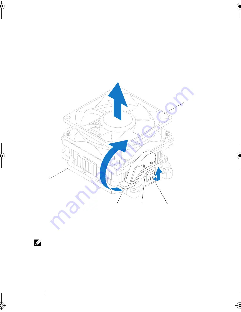
5
Rotate the clamp lever 180 degrees clockwise to release the clamp grip
from the bracket projection.
6
Rotate the processor fan and heat sink assembly upward gently, and
remove it from the computer. Lay the processor fan and heat sink assembly
down on its top, with the thermal grease facing upward.
NOTE:
The processor fan and heat sink assembly in your computer may not look
exactly like the one shown in the illustration above.
1
bracket
2
clamp lever
3
clamp grip
4
bracket projection
5
processor fan and heat sink assembly
3
4
2
5
1
book.book Page 52 Monday, November 19, 2012 11:42 AM
Summary of Contents for Dimension 2010
Page 10: ...10 Technical Overview ...
Page 14: ...14 Before You Begin ...
Page 18: ...18 Computer Cover ...
Page 24: ...24 Memory Module s ...
Page 41: ...Drives 41 ...
Page 42: ...42 Drives ...
Page 44: ...44 Power Switch Module 1 hard drive activity light 2 holder 1 2 ...
Page 46: ...46 Power Switch Module ...
Page 50: ...50 Front I O Panel ...
Page 60: ...60 System Board 9 Lift the system board up and out 1 screws 6 2 system board 1 2 ...
Page 62: ...62 System Board ...
Page 66: ...66 Power Supply ...
Page 78: ...78 System Setup ...


