background image

44

Monitoring 
 

If you are fortunate enough to have SD/HD SDI monitors then you can monitor Inputs 1 to 5 directly from the 
loop through outputs, if however you are inhibited by the cost of these monitors, you can use composite 
monitors such as the Datavideo TLM 433. 
The six built in format standard converters allow you to down convert your inputs to composite or component, 
for easy monitoring. 
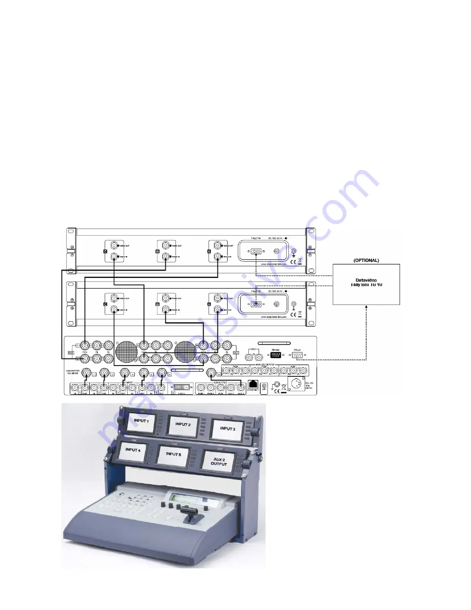
The diagram below shows the recommended set up for monitoring Inputs 1 to 5 plus the auxiliary (AUX) 
Output. 
The auxiliary output can display any of the seven crosspoint channels, the preview channel or the program 
channel (see 

Assigning a signal to the Auxiliary Output)

, so it gives maximum versatility to your 

monitoring set up. With this set up it would be easy to monitor the DVI input, or quickly switch to preview or 
program output monitoring. 
 
The loop through outputs of Inputs 1 to 5 are connected to the format standard converter inputs 1 to 5. The 
AUX 2 output is connected to format standard converter input 6. 
The format standard converter outputs are set to composite; and they are connected to two TLM-433 monitor 
banks. 
The optional Datavideo TB-10 Tally Box can provide tally indication to the TLM-433 monitor banks; there is a 
tally LED above each monitor. 


Summary of Contents for SE-1000

Page 1: ...HD SD Digital Video Switcher SE 1000 Instruction Manual http www datavideo tek com Rev 150507...

Page 2: ...7 15 IP Address Settings 21 Menu 8 15 MASK Settings 21 Menu 9 15 GW GATEWAY Settings 22 Menu 10 15 Displaying the MAC Address 22 Menu 11 15 BUS Mode Settings A B P P 22 Menu 12 15 System Backlight VAN...

Page 3: ...ting the Brightness Standard Definition Output Only 39 Setting Colour Saturation Standard Definition Output Only 39 Setting Tint NTSC Composite Video Output Only 40 Setting an Output to Colour Bar Sta...

Page 4: ...nnector 62 Troubleshooting FAQ 63 No power 63 No image at output 63 Alarm Lights is On 63 Useful Accessories 64 TLM 433 TLM 433JF Monitor Bank Monitor Holder 64 TB 10 Tally Box 64 ITC 100 8 Channel Ta...

Page 5: ...elf Opening or removing covers that are marked Do Not Remove may expose you to dangerous voltage points or other risks and will void your warranty Refer all service issues to qualified service personn...

Page 6: ...material charges at the Buyer s expense This warranty does not affect your statutory rights within the Country of purchase Disposal Disposing of this product correctly will help to save valuable resou...

Page 7: ...ollow and ideal for a live environment Six Inputs five inputs of HD SD SDI and one DVI Six HD SD SDI HD SD Component YUV Composite video converters These allow SD monitors to be used for monitoring th...

Page 8: ...ble 3m x 1 4 AC DC switching adapter 12V 10A x 1 5 Power cord x 1 6 Image Transfer Software CD 7 Instruction manual x 1 Version B 1 SE 1000 switcher x 1 2 Aluminium Carrying Case 3 BNC to BNC 14 5cm c...

Page 9: ...s Make sure you don t run video audio cables and power lines together on top of each other or across each other This is another good way to introduce noise and signal degradation Cable connectors will...

Page 10: ...en power is On the Power Light 2 should light up You will notice that the power switch has been designed to prevent the SE 1000 from being accidentally switched off 2 Power and Alarm LEDs The Power LE...

Page 11: ...is active it is illuminated amber If the WIPE button 8 is selected the Mix button will go out When the AUTO button 10 or T Bar 11 is operated a cross dissolve will be executed 8 WIPE button This is u...

Page 12: ...reen and the setting menu of the function indicated below the button appears on the LCD display TIME For setting the auto transition time WIPE For setting the wipe border and soft effect CBGD For sett...

Page 13: ...ut Connecters PGM 1 26 HD SD YUV Component Analogue PVW Preview Output Connecters PVW 27 HD SD YUV Component Analogue AUX Auxiliary Output Connecters AUX 1 28 Ethernet 10 100 Port This is used for imp...

Page 14: ...the SE 1000 via the REF In port The external signal is looped through so that it may be fed into other devices When the SE 1000 is set to Internal Sync Mode INT both REF ports supply BB outputs so tha...

Page 15: ...d Converter Adjustment Knob We will start by looking at the various menus that are displayed on the main LCD panel Powering Up Using the supplied power cord connect the 12V 10A power supply to a suita...

Page 16: ...panel should look like this The LCD panel shows information in a uniform fashion In the upper left corner is the menu name which refers to the section that the menu adjusts In the example above IN1 5...

Page 17: ...g to the type of signal you want to use Use Adjustment Knob F2 to change the setting You can set the scaling of the DVI image to normal NORM or full FULL by rotating Adjustment Knob F3 please see the...

Page 18: ...t AVDL which will adjust the input signal phase to the horizontal synchronisation reference signal phase Please also refer to Menu 6 15 Output Phase Adjustment Set Up Menu 4 15 Video Format Setting Pr...

Page 19: ...reference signal will be required There are three external modes available BBST Black Burst Signal vertical phase of 0H BBAD Black Burst Signal vertical phase of 90H for 59 94i p formats or 75H for 5...

Page 20: ...utput in phase In this mode the frame synchroniser should be ON for all inputs 1H The output video signals are output to the system REF signal output with 1H delay You can adjust Horizontal Phase HPHS...

Page 21: ...20 Phase Adjustment Set Up Diagram...

Page 22: ...the new value is stored To leave the menu press the FUNC button so that it is no longer illuminated Menu 8 15 MASK Settings Press the FUNC button so that it is illuminated and then press the SET UP b...

Page 23: ...he disappear which confirms the new value is stored To leave the menu press the FUNC button so that it is no longer illuminated Menu 10 15 Displaying the MAC Address Press the FUNC button so that it i...

Page 24: ...em Settings for LCDBacklight VANC BB 0 7 5 ire The SYS System menu contains three settings Backlight On Off VANC On Off and BB Press the FUNC button so that it is illuminated and then press the SET UP...

Page 25: ...ter the vertical position VPOS of the DVI input To leave the menu press the FUNC button so that it is no longer illuminated Menu 14 15 INIT Initialise SE 1000 Init will return the SE 1000 to its facto...

Page 26: ...Menus Setting The Crosspoints Crosspoint assignments determine which signal is routed to which button The settings that you can see below are the default settings You can choose to route the signals i...

Page 27: ...Test Pattern Internally Generated FMEM Frame Memory Image see MEM Menus FMEM 3 3 Frame Memory Page 27 To leave the menu press the FUNC button so that it is no longer illuminated Menu 3 3 XPTAS Crossp...

Page 28: ...es Key Type TYPE LIN Key Adjustment ADJ GAIN 100 CLIP 0 DENS 100 Inversion ON OFF OFF Fill Colour BLE Blue Edge Colour YLW Yellow Edge ON OFF TYPE OFF KEY Edge Width 4 User Colour 1 HUE SAT LUM 0 0 10...

Page 29: ...on the PGM A and PST B rails will change when a preset memory is recalled Press the FUNC button so that it is illuminated and then press the MEM button so that it is also illuminated Rotate Adjustment...

Page 30: ...layed To leave the menu press the FUNC button so that it is no longer illuminated Menu 2 2 FRZ Assigning Freeze Frames To assign freeze frames Press the FUNC button so that it is illuminated and then...

Page 31: ...he menu press the FUNC button so that it is no longer illuminated Menus 2 5 to 5 5 USR1 to USR4 Setting Custom Colours The following settings apply to CBGD Menus 2 5 to 5 5 EDGE Menus 2 5 to 5 5 KEY M...

Page 32: ...he colour change gradually through blues greens yellows and finally back to reds N B if saturation SAT or Luminance LUM is set to 0 you will not see any colour changes Rotate Adjustment Knob F3 to alt...

Page 33: ...w ON Images with Key Effects added are output to preview OFF Images are output to preview without Key Effects added To leave the menu press the FUNC button so that it is no longer illuminated Menu 2 7...

Page 34: ...stom colours To leave the menu press the FUNC button so that it is no longer illuminated Menu 4 7 7 7 USR1 to USR4 Setting Custom Colours These settings are covered in CBGD Menus Menus 2 5 to 5 5 USR1...

Page 35: ...ne just a border with no fill is added around the entire key object Rotate Adjustment Knob F3 to select the width of the edge that you require Rotate Adjustment Knob F4 to select the colour of the edg...

Page 36: ...on so that it is no longer illuminated Menu 2 5 5 5 USR1 to USR4 Setting Custom Colours These are the same settings that are used in EDGE KEY and CBGD Settings These settings are covered in CBGD Menus...

Page 37: ...inated Menu 2 5 Key Time Setting Press the FUNC button so that it is illuminated and then press the TIME button so that it is also illuminated Rotate Adjustment Knob F1 until BKGD 1 5 is displayed Rot...

Page 38: ...at standard converter appear in the small LCD panel above the T Bar and the adjustments are made using the Format Standard Converter Adjustment Knob When the SE 1000 boots up you will see the status d...

Page 39: ...ng adjusts the black level of the video output generally NTSC in North America uses 7 5 ire and NTSC in Japan uses 0 ire If you are unsure of which setting to use please refer to the instruction manua...

Page 40: ...screen will display the new value To Exit the set up menu rotate the Adjustment Knob anti clockwise until FN13 EXIT is displayed and then press the Adjustment Knob Note If no adjustments are made wit...

Page 41: ...s the Adjustment Knob to bring up the Format Standard Converter Adjustment Menu and rotate the Adjustment Knob until FN06 is displayed Press the Adjustment Knob and rotate it to select the required se...

Page 42: ...no adjustments are made within 20 seconds the LCD will return to the status display automatically Setting an Output to Crosshatch High Definition Output Only Each of the output channels can be set to...

Page 43: ...en press the Adjustment Knob Note If no adjustments are made within 20 seconds the LCD will return to the status display automatically Checking Main and Control Firmware Versions Occasionally you may...

Page 44: ...To Exit the set up menu rotate the Adjustment Knob anti clockwise until FN13 EXIT is displayed and then press the Adjustment Knob Note If no adjustments are made within 20 seconds the LCD will return...

Page 45: ...play any of the seven crosspoint channels the preview channel or the program channel see Assigning a signal to the Auxiliary Output so it gives maximum versatility to your monitoring set up With this...

Page 46: ...e the T Bar to perform a manual transition from one source to another You can select between Wipe or Mix Wipe will perform a wipe with the selected wipe pattern There are nine preset wipe patterns to...

Page 47: ...notice that both buses become live this is because both sources are in use When the T Bar has fully traversed from top to bottom or bottom to top the SE 1000 will return to having one live bus and on...

Page 48: ...between Wipe or Mix press the Wipe or Mix button the selected option will be illuminated amber In this example Mix is selected You will also notice that the background BKGD button is illuminated Sele...

Page 49: ...the KEY F FILL is a video source assigned to XPT 6 the live source is a video source assigned to XPT 7 and the cued source is a video source assigned to XPT 5 Once you have set your KEY S and KEY F s...

Page 50: ...ltaneously so that they are both illuminated Mix or Wipe will also be illuminated according to the effect that you have selected You can see that XPT 7 is live and XPT 5 is cued In this mode the cued...

Page 51: ...with any KEY images removed To assign an output to Auxiliary Press and hold the AUX button so that it is illuminated While holding the AUX button in press the button of the source that you want to as...

Page 52: ...ch crosspoints are set to freeze frame in FRZ Menu 1 2 Rotate Adjustment Knob F1 so that FRZ 1 2 is displayed An above the crosspoint number indicates that a freeze frame is assigned In the example ab...

Page 53: ...every possible permutation but many of the principles shown in these diagrams can be used in other set ups On page 44 Monitoring there is an example of how to utilise the six built in Format Standard...

Page 54: ...d using DVI The ITC 100 is providing talkback communication between the crew and the director and also tally light indication for the crew and talent The PGM HD Component output is fed to the Datavide...

Page 55: ...e the SE 1000 is relying upon external sync all the sources are connected to a signal generator which is also connected to the SE 1000 The 4 cameras and playback VTR are connected using HD SDI and the...

Page 56: ...created on a PC and then imported into the SE 1000 You can also use it to save a still image from the SE 1000 to your PC which you could then use to create a DVD sleeve PC Requirements Windows 2000 o...

Page 57: ...192 168 0 10 if you have changed the settings then you will need to use your own values All PCs are slightly different but as a rough guide your PC should like something like this If you are unsure o...

Page 58: ...ent at least you will be able to set everything back to the way it was if you do anything wrong Click on Use the following IP address and enter the details as shown this assumes that the SE 1000 has n...

Page 59: ...er exe You will see the IP Address at the bottom of the screen The IP Address should match the SE 1000 which is 192 168 0 10 In this example the IP address is 192 168 1 10 and therefore does not match...

Page 60: ...are importing an image that is not the right shape to fill the screen you can choose to stretch the image or maintain its aspect ratio and have black bars either side The image attributes appear just...

Page 61: ...ar should appear and after a while an ImgTransfer OK box should appear Click on the OK box to complete the process Transferring an image from the SE 1000 To transfer an image from the SE 1000 to a PC...

Page 62: ...systems such as the Datavideo ITC 100 Please see Useful Accessories for further details of TLM 433 TB 10 ITC 100 RS 422 RS 422 enables the SE 1000 to be controlled from external devices The RS 422 po...

Page 63: ...monitors or the ITC 100 Talkback system See Useful Accessories for more details of the TLM 433 ITC 100 TB 10 The data format is as follows Pin No Signal Name Input Output Type Description of Signal 1...

Page 64: ...th of the inlet cables are connected to the PD 1 No Video Output Since the SE 1000 is unable to accept multiple input formats it is important that the input formats match the intended output format Fo...

Page 65: ...i Colour Tally Light above it to indicate the Live and Cued sources The monitors are mounted in a TLM 433JF LCD Holder which attaches to the SE 1000 and provides mounts for the 2 x TLM 433 plus room f...

Page 66: ...member of the camera crew would be wearing Features Industry Standard 19 1U rack design for easy integration Supports 8 Way Intercom standard package includes 4 sets of ITC 100SL with belt pack access...

Page 67: ...deo input Reference 1 x Black Burst TRI with loop through Main Outputs SDI 3 x Outputs PGM x 2 PVW x 1 plus AUX x 2 HD Analogue 3 x Outputs Y Pb Pr HD only PGM x 1 PVW x 1 AUX x 1 Reference Loop throu...

Page 68: ...720 50p Aspect Converter Input SD 16 9 or 4 3 Output SD 16 9 or 4 3 IRE 0 7 5 IRE Options NTSC Only Operating Temperature 0 C to 40 C 32 F to 102 F Humidity 10 to 90 non condensing Power DC 12V 10A Di...

Page 69: ...erside Business Park Hadfield Glossop Derbyshire SK13 1BE UK Tel 44 1457 851000 sales datavideo co uk www datavideo info Datavideo Technologies Co Ltd 10F 176 Jian Yi Rd Chung Ho City Taipei Hsien Tai...

Reviews: