

DI–720/DI–722/DI–730 Series User Manual
Accessories
73
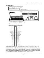
DI-75B Rear Panel
Removable Screw Terminal Block
— Allows signal connections to be made to the DI-75B. The input signal con-
nections are made along the top row while the excitation connections (for those DI-5B modules that require excita-
tion) are made along the bottom row. Note that this screw terminal block can be removed from the DI-75B, thus
making signal connections to the screw terminals easy. Note also that the screw terminal block is “keyed,” thus diffi-
cult to improperly re-insert. Each channel (labeled “CHANNEL 1,” “CHANNEL 2,” etc. on the socketed backplane)
has four corresponding screw terminals for your signal connections: c, channel -, exci, and excitation
-. These terminals satisfy all transducer inputs and provide sensor excitation when necessary.
Summary of Contents for DI-725/E
Page 2: ......
Page 4: ......
Page 6: ......
Page 10: ......
Page 32: ......
Page 40: ......
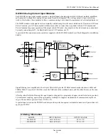
Page 45: ...DI 720 DI 722 DI 730 Series User Manual Block Diagram 35 6 Block Diagram DI 720 Series 1 32...
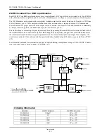
Page 46: ...DI 720 DI 722 DI 730 Series User Manual Block Diagram 36 DI 722 Series...
Page 106: ......
Page 107: ......


