
DI–720/DI–722/DI–730 Series User Manual
Accessories
68
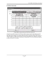
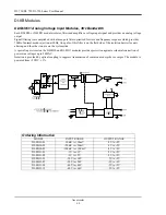
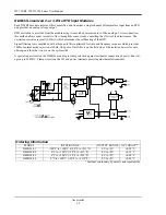
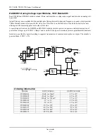
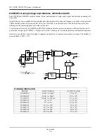
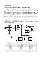
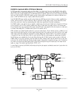
DI-8B45 Frequency Input Modules
Each DI-8B45 module isolates and conditions a frequency input signal and provides an analog voltage output.
The frequency input signal can be either a TTL level or zero crossing with as little as ±100mV amplitude. Input cir-
cuitry for each signal type has built-in hysteresis to prevent spurious noise from corrupting the module output. TTL
signals are applied to the + and - terminals while zero crossing signals are applied to the +EXC and - terminals. Ref-
erence the block diagram.
A 5V excitation is available for use with magnetic pick-up or contact closure type sensors. The excitation is available
on the -EXC terminal with return on the - terminal.
A special input circuit on the DI-8B45 modules provides protection against accidental connection of power-line volt-
ages up to 240VAC. Clamp circuits on the I/O and power terminals protect against harmful transients.
Isolation is provided by optical coupling to suppress transmission of common mode spikes or surges. The module is
powered from +5VDC, ±5%.
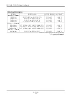
Ordering Information
MODEL
INPUT RANGE
OUTPUT RANGE
EXCITATION
DI-8B45-01
0 to 500Hz
0 to +5V
+5V at 8mA max
DI-8B45-02
0 to 1kHz
0 to +5V
+5V at 8mA max
DI-8B45-03
0 to 2.5kHz
0 to +5V
+5V at 8mA max
DI-8B45-04
0 to 5kHz
0 to +5V
+5V at 8mA max
DI-8B45-05
0 to 10kHz
0 to +5V
+5V at 8mA max
DI-8B45-06
0 to 25kHz
0 to +5V
+5V at 8mA max
DI-8B45-07
0 to 50kHz
0 to +5V
+5V at 8mA max
DI-8B45-08
0 to 100kHz
0 to +5V
+5V at 8mA max
Summary of Contents for DI-725/E
Page 2: ......
Page 4: ......
Page 6: ......
Page 10: ......
Page 32: ......
Page 40: ......
Page 45: ...DI 720 DI 722 DI 730 Series User Manual Block Diagram 35 6 Block Diagram DI 720 Series 1 32...
Page 46: ...DI 720 DI 722 DI 730 Series User Manual Block Diagram 36 DI 722 Series...
Page 106: ......
Page 107: ......


