


DI–720/DI–722/DI–730 Series User Manual
Getting Started
19
11. Select the destination directory where you would like all folders and files to reside on your hard drive. We rec-
ommend you accept the default path, but you can name this new directory anything you like. Simply substitute
the desired drive and directory in the Destination Directory text box. Once you have chosen the directory click
OK
.
12. The “Make Backups?” dialog box provides the option of creating backup copies of any files that may be replaced
during installation. This is a safety courtesy; backup copies are not required. Click on
No
if you don't want to
make backups. Click on
Yes
to create backups. If you decide to create backups, you will be prompted to specify
a backup file directory.
13. Select the program manager group you would like to place the program shortcuts in your Windows programs.
The default is recommended, but you can specify any program group or create a new one. Click
OK
to continue.
14. You must know either the MAC address or the IP address of the device to continue. The MAC address is located
on the sticker on the bottom of your device. IP addresses must be retrieved from the system administrator. Enter
the MAC address or IP address in the text box provided in the “MAC or IP address of the device” dialog box. If
you are installing a device that is not connected to your Local Area Network, you should enter the IP address
here. The software will go to that IP address and retrieve the MAC address for you. This will save further setup
in the TCP/IP Manager. Click
OK
to continue.
Note: If you enter the wrong MAC address you will have to re-run
this installation program with the correct MAC address to access the device.
15. Click
Yes
in the “More ethernet devices to install” dialog box if you are installing multiple Ethernet devices.
16. Repeat Steps 14 and 15 until all Ethernet devices’ MAC addresses have been entered. Click
No
to continue
installation.
17. The “Installation Option” dialog box allows you to specify access to W
IN
D
AQ
for multiple users on the same PC.
If you are the only user or you would like to allow access to all users click
Yes
. If there are multiple users and
you would like to be the only one able to access W
IN
D
AQ
click
No
. Click
Cancel
to abort the installation.
18. Select the desired options for installation of W
IN
D
AQ
/XL and Advanced CODAS.
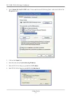
19. Installation is complete. Run the TCP/IP Manager via the Windows program group specified during W
IN
D
AQ
Software installation (default is
Start > Programs > WINDAQ > IP Manager
) to access the device and run
W
IN
D
AQ
Acquisition Software
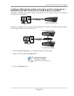
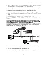
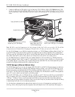
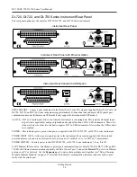
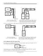
Daisy-Chaining Multiple Ethernet Products
Multiple Ethernet products may be daisy-chained together to allow for one synchronous distributed data acquisition
system. Multiple DI-720, DI-722, and/or DI-730 instruments may be placed in the same daisy chain. To maintain syn-
chronicity, Ethernet hubs and switches cannot be used between units. Make sure to enter each MAC address during
installation. Daisy-chains must be installed to your Local Area Network (LAN) — you cannot access more than one
device per IP address outside of your subnet. If you are not sure whether or not the devices are in your subnet see your
system administrator before installation. You may acquire data from only one daisy chain at a time (i.e., the same PC
cannot access two daisy chained groups at the same time).
Note: If you are installing a daisy-chained group of instruments for the purpose of synchronous distributed data
acquisition, do not allow any other units or daisy chains to be installed to your subnet. Running other devices on the
same subnet will cause the synced units to become unsynced.
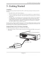
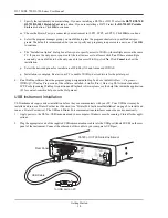
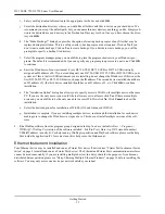
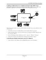
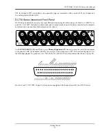
1.
Connect one end of a CAT-5 Ethernet cable to the
Toward PC
port of the first Ethernet device.
2.
Connect the other end of the same CAT-5 Ethernet cable to the Ethernet port on your PC or LAN.
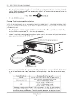
3.
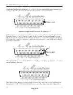
Connect one end of another CAT-5 Ethernet Cable to the
Expansion
port on the rear of the first Ethernet device.
4.
Connect the other end of the same CAT-5 Ethernet cable to the
Toward PC
port on the second Ethernet device.
Summary of Contents for DI-725/E
Page 2: ......
Page 4: ......
Page 6: ......
Page 10: ......
Page 32: ......
Page 40: ......
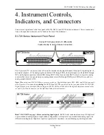
Page 45: ...DI 720 DI 722 DI 730 Series User Manual Block Diagram 35 6 Block Diagram DI 720 Series 1 32...
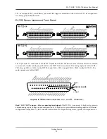
Page 46: ...DI 720 DI 722 DI 730 Series User Manual Block Diagram 36 DI 722 Series...
Page 106: ......
Page 107: ......


