


DI–720/DI–722/DI–730 Series User Manual
Calibration Verification
31
5. Calibration Verification
This section provides calibration verification procedures for the A/D and D/A subsystems of the DI-7xx unit. Your
instrument is calibrated before it is shipped and, therefore, does not need immediate calibration. Should your unit not
comply with the calibration guidelines presented below, arrange to have DATAQ Instruments recalibrate your instru-
ment.
Required Equipment
A/D Calibration (For DI-720, DI-722, and DI-730 Series Instruments)
•
A precision DVM with resolution as a function of the input range being calibrated:
minimum DVM resolution = Instrument FSR x 0.1%
For example, suppose we have a DI-720-P and we want to calibrate the ±10 volt range (the DI-720 delivers ±10
volts at a gain of 1):
10V x 0.1% = 10mV
So we would need a DVM with a resolution of 10V or more to calibrate the ±10 volt range.
•
A stable voltage source with a stability specification equal to or greater than the minimum DVM resolution,
as calculated above, required to calibrate the instrument at the highest desired gain.
OR
•
An alternative is to use a voltage calibrator with enough resolution, as calculated above, to calibrate the
instrument at the highest desired gain.
D/A Calibration (DI-720 Instruments Only)
•
A precision DVM with resolution of at least 1mV.
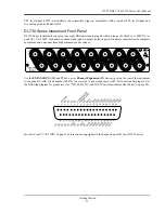
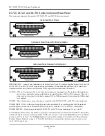
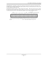
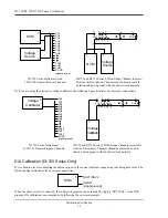
A/D Calibration Verification (DI-720, DI-722, and DI-730 Series Instruments)
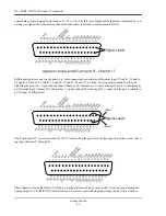
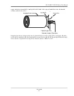
Calibration verification of DI-720 Series instruments' A/D subsystem is performed on channel 1, with all other chan-
nels returned to analog common. Calibration of DI-730 Series instrument's A/D subsystem is performed on a chan-
nel-by-channel basis for the 8 wide range inputs and on channel 17 for the general-purpose channels. The following
figures illustrate the necessary connections:
Summary of Contents for DI-725/E
Page 2: ......
Page 4: ......
Page 6: ......
Page 10: ......
Page 32: ......
Page 40: ......
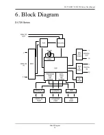
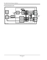
Page 45: ...DI 720 DI 722 DI 730 Series User Manual Block Diagram 35 6 Block Diagram DI 720 Series 1 32...
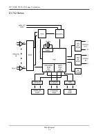
Page 46: ...DI 720 DI 722 DI 730 Series User Manual Block Diagram 36 DI 722 Series...
Page 106: ......
Page 107: ......


