


DI–720/DI–722/DI–730 Series User Manual
Getting Started
28
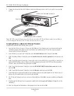
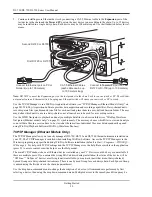
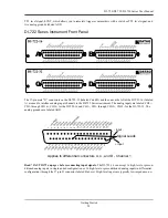
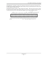
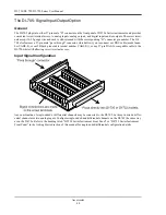
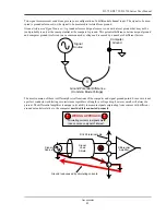
DI-720, DI-722, and DI-730 Series Instrument Rear Panel
The rear panel options are the same for DI-720, DI-722, and DI-730 Series instruments:
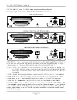
PRINTER PORT—Connects your instrument to the Printer Port of your PC using the supplied Printer Port Cable. All
DI-720, DI-722, and DI-730 Series instruments support standard, bi-directional and enhanced (EPP) printer port
communication modes (Ethernet and USB models only support bi-directional and EPP modes).
ACTIVE—DI-7xx-P instruments: Glows red when the instrument is streaming data. This includes all digital input/
output (where applicable), analog output and analog input functions. DI-7xx-EN instruments: Glows red
whenever data is sent back to the host computer. DI-7xx-USB instruments: Glows when the USB control-
ler is enabled.
POWER—This indicator glows green when power is applied to the DI-720, DI-722, or DI-730 Series instrument.
POWER INPUT JACK—Allows you to apply power to the instrument. Power can be applied with the included
power adapter or you can use an alternate source, as long as it is suitable (+9 to +36VDC @ 3A maximum).
POWER SWITCH—Controls power to the DI-720, DI-722, or DI-730 Series instrument. 1 is on, 0 is off.
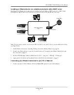
CAT-5 Ethernet (EN models)—In addition to printer port communications, models DI-720-EN, DI-722-EN, and DI-
730-EN add Ethernet communication capability with this 10baseT port. Connect the
Toward PC
port to an Ethernet
port on your PC or Network. Use the
Expansion
port to daisy-chain multiple units together (see “Daisy-Chaining
Multiple Ethernet Products” on page 19). Note that the Ethernet communication interface cannot be used concur-
rently with the printer port.
Instrument Rear Panel
Instrument Rear Panel with Ethernet Option
Instrument Rear Panel with USB Option
Summary of Contents for DI-725/E
Page 2: ......
Page 4: ......
Page 6: ......
Page 10: ......
Page 32: ......
Page 40: ......
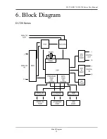
Page 45: ...DI 720 DI 722 DI 730 Series User Manual Block Diagram 35 6 Block Diagram DI 720 Series 1 32...
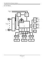
Page 46: ...DI 720 DI 722 DI 730 Series User Manual Block Diagram 36 DI 722 Series...
Page 106: ......
Page 107: ......


