


DI–720/DI–722/DI–730 Series User Manual
Getting Started
23
4. Instrument Controls,
Indicators, and Connectors
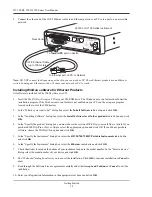
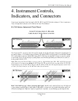
Connect most signal leads to the front panel of DI-720, DI-722, and DI-730 Series instruments. Power, communica-
tions, and expansion connectors can be found on the rear of the instrument.
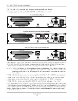
DI-720 Series Instrument Front Panel
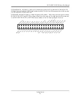
The 37-pin male “D” connector on the left is used to interface analog input channels 1 through 16, digital inputs 1-8,
and digital outputs 1-8. The analog inputs are labeled CH1 through CH16, the digital inputs are labeled DI0 through
DI7, and the digital outputs are labeled DO0 through DO7. Other items include DAC2, which is a digital to analog
converter that serves as a general-purpose analog output accessible through W
IN
D
AQ
and SDK software, and two
analog grounds labeled AGD.
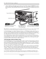
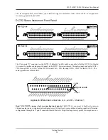
Note: When using your DI-720-USB as a printer port device, Digital Output ports DO1, DO2, and DO3 are unavail-
able. If you have an expander (excluding the DI-78B and DI-75B) connected via the rear panel of the DI-720-USB,
Digital Output is not available. When using your DI-720-USB as a USB device the digital outputs are moved to the
second 37 pin D-sub connector (on the right hand side of the instrument).
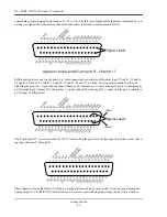
Read “CAUTION” on page v before connecting input signals
. DI-720 Series instruments can accept 32 high-level
or preconditioned analog inputs in single-ended configuration or 16 high-level or preconditioned analog inputs in a
differential configuration. High-level inputs are typically low impedance, no-conditioning-required signals in the
Connect 16 single-ended or 8 differential
inputs directly to each of these connectors.
Summary of Contents for DI-725/E
Page 2: ......
Page 4: ......
Page 6: ......
Page 10: ......
Page 32: ......
Page 40: ......
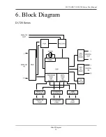
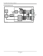
Page 45: ...DI 720 DI 722 DI 730 Series User Manual Block Diagram 35 6 Block Diagram DI 720 Series 1 32...
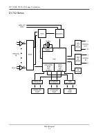
Page 46: ...DI 720 DI 722 DI 730 Series User Manual Block Diagram 36 DI 722 Series...
Page 106: ......
Page 107: ......


