


DI–720/DI–722/DI–730 Series User Manual
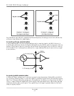
Calibration Verification
32
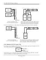
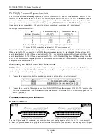
Or if you are using the alternative voltage calibrator, the following figure illustrates the necessary connections:
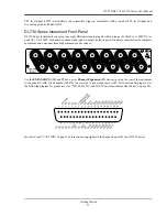
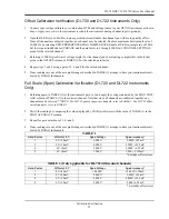
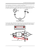
D/A Calibration (DI-720 Series Only)
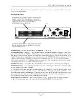
D/A calibration involves adjusting the analog outputs to the correct full-scale range using the analog data value. The
following figure illustrates the necessary connections:
When the above circuit is connected, the calibration program can be initiated by typing “DI720CAL” at the DOS
prompt. D/A calibration is accomplished by following the on screen prompts.
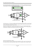
DI-720 Series Instruments And
16 DI-730 General-Purpose Channels
DI-722 and DI-730 Series 8 Wide-Range Channels (accessi-
ble from the front panel). Channels should be measured in
isolation and not in groups with the shortest lead possible.
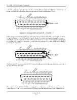
DI-720 Series Instruments
16 DI-730 General-Purpose Channels
DI-722 and DI-730 Series 8 Wide-Range Channels (accessible
from the front panel). Channels should be measured in isola-
tion and not in groups with the shortest lead possible.
CH1
CH2
CH3
CH4
CH5
CH6
CH7
CH8
CH9
CH30
CH31
CH32
S.GND
(signal ground)
Voltage
Source
+
+
-
-
DVM
DVM
Voltage
Source
+
+
-
-
CH1 CH2 CH3
CH8
+
+
+
+
-
-
-
-
+
-
CH1
CH2
CH3
CH4
CH5
CH6
CH7
CH8
CH9
CH30
CH31
CH32
S.GND
(signal ground)
Voltage
Calibrator
Voltage
Calibrator
+
-
CH1 CH2 CH3
CH8
+
+
+
+
-
-
-
-
+
-
DVM
DAC1/DAC2
SGND
(signal ground)
Summary of Contents for DI-725/E
Page 2: ......
Page 4: ......
Page 6: ......
Page 10: ......
Page 32: ......
Page 40: ......
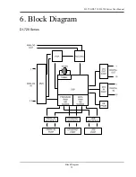
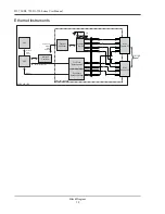
Page 45: ...DI 720 DI 722 DI 730 Series User Manual Block Diagram 35 6 Block Diagram DI 720 Series 1 32...
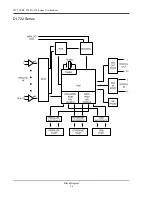
Page 46: ...DI 720 DI 722 DI 730 Series User Manual Block Diagram 36 DI 722 Series...
Page 106: ......
Page 107: ......


